西门子SIPLACE S25 HM-设备性能参数_EN - 第28页
26 Description Various factors contribute to the placement accur acy of the SIPLACE S-25 HM machine, e.g., the stationar y PCB during the placement process. As no accel- erations are acti ng on the placed components, the…

25
Description
The standard component vision
module is directly integrated into
the Collect & Place Head. While
the component is cycling into the
next station of the Collect & Place
Head, the recorded image is eva-
luated by the central vision sys-
tem. The component rotation is
then corrected by the appropriate
angle based on the position off-
sets determined with vision in-
spection.
Vision Sensor Technology:
Standard Component Vision Modules for 12- and 6-Nozzle
Collect & Place Head
Standard Component Vision Module for the 12-Nozzle C & P Head
Maximum component size 18.7 x 18.7 mm
2
Component Range See table on page 6
Camera’s field of view 24 x 24 mm
2
Illumination Front lighting
(3 freely programmable planes)
Standard Component Vision Module for the 6-Nozzle C & P Head
Maximum component size 32 x 32 mm
2
Component Range See table on page 6
Camera’s field of view 39 x 39 mm
2
Illumination Front light
(2 freely programmable planes)
26
Description
Various factors contribute to the
placement accuracy of the
SIPLACE S-25 HM machine, e.g.,
the stationary PCB during the
placement process. As no accel-
erations are acting on the placed
components, their position contin-
ues unchanged. The PCB moves in
and out at a coordinated speed
which is automatically reduced just
before the nominal position is
reached.
A further guarantee for long-term
high placement accuracy is the
position recognition of the axes of
the gantry and placement head by
means of optical scanning by in-
cremental encoders. Revolving
star and segments of the Collect
& Place Head are positioned by
means of high-resolution glass in-
cremental panels. The X- and Y-
axes are positioned with the help
of the metal scales on each gantry
axis.
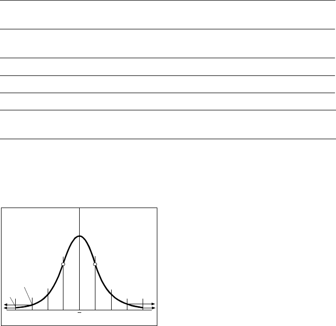
To determine the placement accu-
racy on SIPLACE machines, highly
precision glass components with
mounted structures are placed on
a dimensionally accurate glass
mapping plate. The results are sta-
tistically evaluated and presented
as a Gaussian standard distribu-
tion. In the case of the 6-Nozzle
Collect & Place Head at the
SIPLACE S-25 HM the placement
accuracy is ± 80 µm at a statistical
reliability of 4 sigma. In other
words, of one million placed com-
ponents, 60 are outside the speci-
fied tolerance (= 60 dpm). If the
accuracy value ± 80 µm is divided
by the sigma value 4, the result is
the standard deviation S of 1
sigma = ± 20 µm.
A machine capability analysis is
conducted for each machine ac-
ceptance test.
Machine Criteria:
Placement Accuracy
Technical Data Gantry
Drive Brushless AC Temperature
Controlled Motor
Position measuring system
(X/Y)
Linear scales
Resolution of X-/Y-axis 2.5 µm
Speed of X-axis max. 2.5 m/s
Speed of Y-axis max. 2.5 m/s
Placement Accuracy see table on page 6
Standard Deviation - dpm
-4
σ
-3
σ
-2
σ
σ
x
σ
2
σ
3
σ
4
σ
2700 dpm
60 dpm
P Point o
f
In
f
lection
27
Description
In addition to correct positioning,
placement reliability is important.
On the SIPLACE S-25 HM this is
ensured through a number of con-
trol functions, such as vacuum
checks and component vision
testing during the placement se-
quence.
Out of tolerance components are
rejected, placed on the repair list
and automatically processed dur-
ing a repair cycle. An offset in the
position of the PCB relative to the
conveyor system (PCB vision) and
an offset of the X-axis, Y-axis or ro-
tation of the component relative to
the midpoint of the nozzle (com-
ponent vision) trigger an immedi-
ate correction to ensure placement
accuracy.
Since the PCB is fixed, the com-
ponents remain in the exact posi-
tion they are placed. The stationary
component table ensures a pre-
cise pick up. Options, such as the
component bar code scanner, can
be added to further enhance reli-
ability.
Placement errors
Placement errorsPlacement errors
Placement errors
Errors that occur after the compo-
nent has been placed on the PCB.
They include:
§ Component is missed on PCB
§ Too many components on PCB
§ Components not placed prop-
erly on PCB
§ Components placed while
standing on edge
Machine Criteria:
Placement Reliability
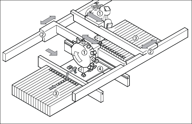
Placement Principle of SIPLACE S-25
HM
➀ 6-Nozzle or 12-Nozzle
Collect & Place Head
➁ X-/Y-Gantry System
➂ Fixed Component Supply
➃ Fixed PCB