西门子SIPLACE S25 HM-设备性能参数_EN - 第30页
28 Description Despite the highl y stable mach ine frame, slight distortions of the gan- try axes cannot alw ays be avoided. With the aid of the m apping proc- ess the high placem ent accur acy of the machine is preserve…
27
Description
In addition to correct positioning,
placement reliability is important.
On the SIPLACE S-25 HM this is
ensured through a number of con-
trol functions, such as vacuum
checks and component vision
testing during the placement se-
quence.
Out of tolerance components are
rejected, placed on the repair list
and automatically processed dur-
ing a repair cycle. An offset in the
position of the PCB relative to the
conveyor system (PCB vision) and
an offset of the X-axis, Y-axis or ro-
tation of the component relative to
the midpoint of the nozzle (com-
ponent vision) trigger an immedi-
ate correction to ensure placement
accuracy.
Since the PCB is fixed, the com-
ponents remain in the exact posi-
tion they are placed. The stationary
component table ensures a pre-
cise pick up. Options, such as the
component bar code scanner, can
be added to further enhance reli-
ability.
Placement errors
Placement errorsPlacement errors
Placement errors
Errors that occur after the compo-
nent has been placed on the PCB.
They include:
§ Component is missed on PCB
§ Too many components on PCB
§ Components not placed prop-
erly on PCB
§ Components placed while
standing on edge
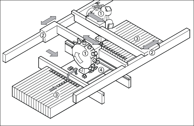
Machine Criteria:
Placement Reliability
Placement Principle of SIPLACE S-25
HM
➀ 6-Nozzle or 12-Nozzle
Collect & Place Head
➁ X-/Y-Gantry System
➂ Fixed Component Supply
➃ Fixed PCB
28
Description
Despite the highly stable machine
frame, slight distortions of the gan-
try axes cannot always be avoided.
With the aid of the mapping proc-
ess the high placement accuracy
of the machine is preserved
throughout its entire service life.
With this calibrating procedure,
which can be conducted quickly
and easily, the PCB camera recog-
nizes the fiducials on a mapping
calibration plate placed in its oper-
ating area. Any distortions are re-
vealed by comparing the nominal
grid on the glass plate with the ac-
tual grid “drawn” by placement
head. These distortions are taken
into account during all further posi-
tioning of X-/Y-axes and thus com-
pensated for.
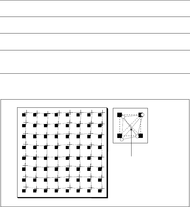
Machine Criteria:
Mapping (Option)
Technical Data
Dimensions of the mapping
test plate
520 x 460 mm
2
(for single conveyor)
520 x 215 mm
2
(for dual conveyor)
Number of measurement
points
13 x 11 (standard resolution)
26 x 21 (high resolution)
Ambient temperature during
calibration + 20° ± 3°C
Components of the option Test plate (special glass)
Calculation data (disk)
Case for secure storage
Nominal Grid of Mapping Plate and Actual Grid with
Deviations Due to Gantry
Corrected
Position
29
Description
The UNIX line computer is as-
signed the following interstation
tasks: creation, revision and man-
agement of placement programs,
job data and component and GF li-
braries; automatic, optimized gen-
eration and administration of ma-
chine set-ups (set-up optimization,
set-up editors, optional set-up se-
quence optimization); determina-
tion of optimized travel for gantry
and nozzle assignments of the
Collect & Place Heads; control and
supply of data to SIPLACE ma-
chines in a line; calculation, stor-
age and display of machine and
operating data; data backup on
built-in magnetic tape drive.
The Windows station computer in
conjunction with the machine con-
troller with its realtime capability
performs the following jobs: digital
control of the machine gantry sys-
tems; control of PCB input and
output and of PCB transport; moni-
toring functions, handling of mal-
functions and output of error mes-
sages (including Help system);
ensuring the optimal quality of the
placement process; optional load-
ing control by means of compo-
nent bar code and optional place-
ment program change by means
of PCB bar code.
For more detailed information
please see “SIPLACE Software
Specification”.
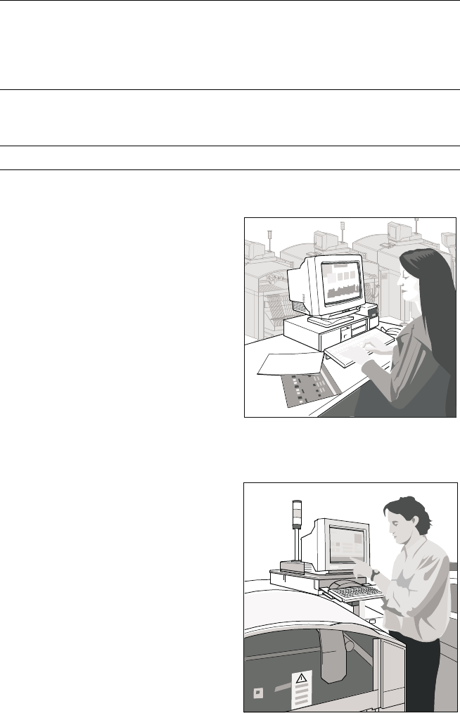
SIPLACE Software Architecture:
Line Computer / Station Computer
Functions
Line computer Programming
Optimization
Line control
Line monitoring
Data management
Station computer Machine control
Machine monitoring
Machine operation
Softwareversion From 502.xx
Line Computer
Station Computer