西门子SIPLACE S25 HM-设备性能参数_EN - 第32页
30 1. After switching-on the station Technical Data: Signal Interfaces Signal Interface (20-Pin Ribbon C able Connector) to upstream station x3 to down stream station x4 Pin 13 GND 24 V Pin 10 Reserved Pin 14 Arrived P i…
29
Description
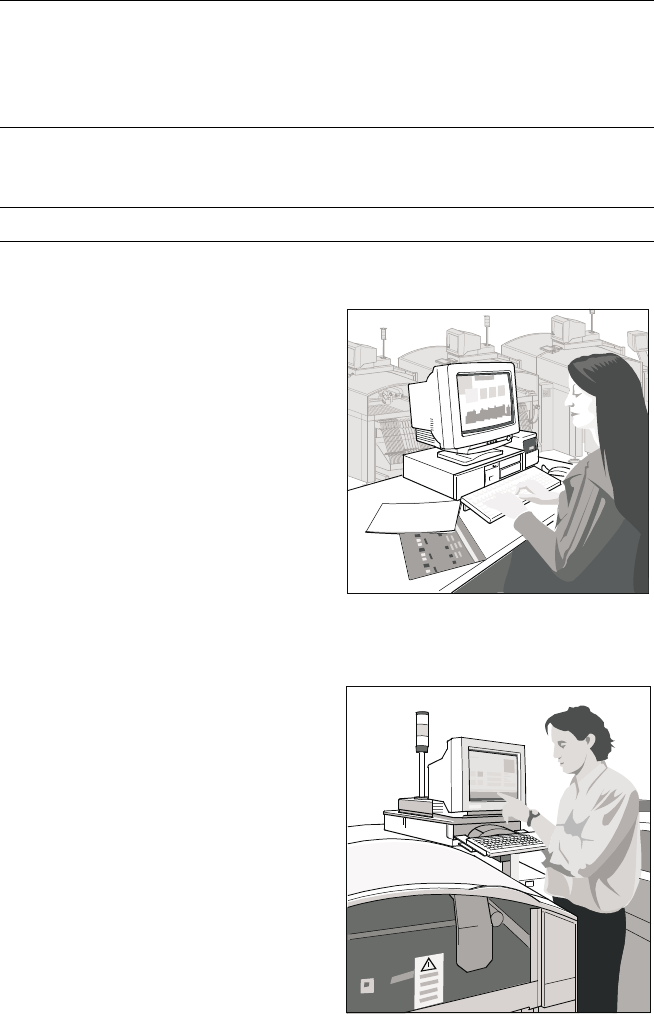
The UNIX line computer is as-
signed the following interstation
tasks: creation, revision and man-
agement of placement programs,
job data and component and GF li-
braries; automatic, optimized gen-
eration and administration of ma-
chine set-ups (set-up optimization,
set-up editors, optional set-up se-
quence optimization); determina-
tion of optimized travel for gantry
and nozzle assignments of the
Collect & Place Heads; control and
supply of data to SIPLACE ma-
chines in a line; calculation, stor-
age and display of machine and
operating data; data backup on
built-in magnetic tape drive.
The Windows station computer in
conjunction with the machine con-
troller with its realtime capability
performs the following jobs: digital
control of the machine gantry sys-
tems; control of PCB input and
output and of PCB transport; moni-
toring functions, handling of mal-
functions and output of error mes-
sages (including Help system);
ensuring the optimal quality of the
placement process; optional load-
ing control by means of compo-
nent bar code and optional place-
ment program change by means
of PCB bar code.
For more detailed information
please see “SIPLACE Software
Specification”.
SIPLACE Software Architecture:
Line Computer / Station Computer
Functions
Line computer Programming
Optimization
Line control
Line monitoring
Data management
Station computer Machine control
Machine monitoring
Machine operation
Softwareversion From 502.xx
Line Computer
Station Computer
30
1. After switching-on the station
Technical Data:
Signal Interfaces
Signal Interface (20-Pin Ribbon Cable Connector)
to upstream station x3 to downstream station x4
Pin 13 GND 24 V Pin 10 Reserved
Pin 14 Arrived Pin 9 Reserved
Pin 15 Permission Pin 8 Reserved
Pin 19 Request Pin 4 +30 V DC
unsaturated
Pin 20 GND 24 V for request / re-
leased (contact separation)
Pin 5 GND 24 V
Pin 18 Released Pin 6 +24 V DC
Pin 12 Trouble signal loop Pin 11 Trouble signal loop
Pin 11 Pin 12
Pin 3 +24 V DC Pin 15 Permission
Pin 2 GND 24 V Pin 13 GND 24 V for per-
mission / arrived
(contact separation)
Pin 1 +30 V DC unsaturated Pin 14 Arrived
Pin 8 Reserved Pin 18 Released
Pin 9 Reserved Pin 19 Released
Pin 10 Reserved Pin 20 GND 24 V
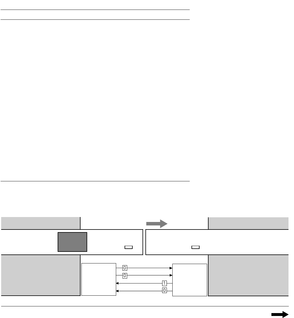
Requirement
Delivery
Permission
Receival
Requirement
Delivery
Permission
Receival
Transport Direction
Conveyor Section 1
PCB
Sensor
PCB
Sensor
Conveyor Section 2
Station n
transports
PCB
to delivery
Station n+1
is ready to
receive PCBs
Conveyor 1 is On Conveyor 2 is Off
31
Technical Data:
Signal Interfaces
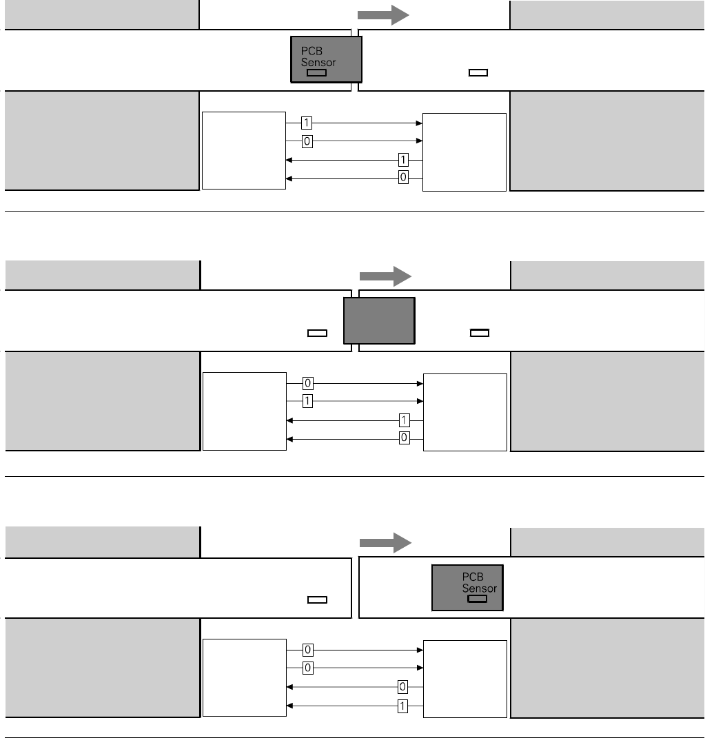
2. PCB handling has started
Conveyor 1 is On Conveyor 2 is On
Transport Direction
Conveyor Section 1
Conveyor Section 2
Station n
delivers PCB
to station n+1
Station n+1
waits for PCB
from station n
Requirement
Delivery
Permission
Receival
Requirement
Delivery
Permission
Receival
PCB
Sensor
Transport Direction
Conveyor Section 1
PCB
Sensor
Conveyor Section 2
Station n
has just
delivered PCB
Station n+1
waits for PCB from
station n, but has
not received it
Requirement
Delivery
Permission
Receival
Requirement
Delivery
Permission
Receival
PCB
Sensor
3. PCB is at delivery
Conveyor 1 is Off Conveyor 2 is On
Conveyor 1 is Off Conveyor 2 is On
Transport Direction
Conveyor Section 1
PCB
Sensor
Conveyor Section 2
Station n Station n+1
has just received
the PCB
Requirement
Delivery
Permission
Receival
Requirement
Delivery
Permission
Receival
4. PCB transport is finished
A detailed documentation of the
PCB transport signal interface is
available on request.