西门子SIPLACE S25 HM-设备性能参数_EN - 第4页
2 Technical Data 30 Signal In terfaces Connection s Dimension s and Set-Up Condition s Transporting and Commi ssioning Possible Mac hine Configuration 35 High Speed SMD Placement System SIPLACE S-25 HM SIPLACE S-25 HM
1
Subject to change
without notice.
Edition 2
1001-S-25-600-e
Order No
E80002-P104-A409-X-7600
Machine Description 3
Line Design 4
Placement Heads 5
Head Modularity
Placement Accuracy
Component Range
12-Nozzle Collect & Place Head for High Speed
Component Placement
6-Nozzle Collect & Place Head for High-Speed Large
Component Placement
Nozzle Changer
PCB Conveyor 10
Single Conveyor
Dual Conveyor
Ceramic Substrate Centering (Option)
PCB Bar Code for Production-Controlled Manufacturing
(Option)
Component Supply 14
Changeover Table
Tape Feeder
Bulk Case Feeder
Stick Magazine Feeder
Guard for Feeder Locations
Matrix Tray Changer (Option)
Component Bar Code Scanner for Set-Up and Refill Check
(Option)
SIPLACE External Set-Up Station (Option)
Vision Sensor Technology 21
PCB Vision Module
PCB Position Recognition
Bad Board Recognition
Position Recognition of Feeder
Algorithms to determine the X-/Y-Position and the Rotation
Angle of Components
Standard Component Vision Modules for 12- and 6-Nozzle
Collect & Place Head
Machine Criteria 26
Placement Accuracy
Placement Reliability
Mapping (Option)
SIPLACE Software Architecture 29
Line Computer / Station Computer
High Speed SMD Placement System
SIPLACE S-25 HM
2
Technical Data 30
Signal Interfaces
Connections
Dimensions and Set-Up Conditions
Transporting and Commissioning
Possible Machine Configuration 35
High Speed SMD Placement System
SIPLACE S-25 HM
SIPLACE S-25 HM

3
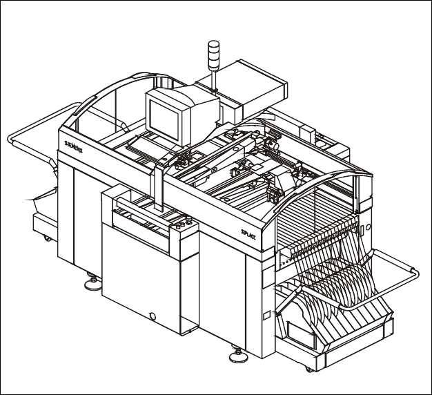
Description
The high-speed SMD placement
system SIPLACE S-25 HM com-
bines high placement speed with
flexibility and accuracy. In contrast
to classic chipshooters, a Collect
& Place procedure is applied here.
SIPLACE S-25 HM placement ma-
chines are equipped with two X-/Y-
main gantries. Each gantry featu-
res a star-shaped Collect & Place
placement head with either 12
or 6 nozzles.
The placement heads alternately
pick up components from the sta-
tionary component feeder and
place components on the PCB
which is also motionless. This has
distinct advantages:
§ Component tapes of all sizes
can be replenished by splicing a
new reel of components to the
end of a depleting reel. This eli-
minates machine stoppage due
to component replenishment.
§ Stationary, vibration-free feed-
ers ensure a reliable pick-up of
even the smallest components
(e.g., 0201 and 0402 chips).
§ Thanks to the flexible Collect
& Place Heads – whose ideal
nozzle set-up is automatically
specified – the travel can be
minimized and the sequence of
placement optimally adjusted.
§ Populating a stationary PCB
also prevents components from
shifting during placement.
Speed coupled with economic ef-
ficiency and set-up reliability is the
SIPLACE S-25 HM recipe for suc-
cess. The first components are al-
ready being picked up while the
PCB is being moved in. While one
Collect & Place Head is placing
components, the other one is
picking components up.
The product capability is enhanced
by optional add-on features such
as component bar code scanner,
automatic nozzle changer or
changeover tables which can be
set up outside the machine and
exchanged in a matter of minutes.
§ Additional changeover tables
enables the reduction of job set-
up time increasing machine
utilisation.
§ Dual Conveyor eliminates the
non-productive PCB loading
times thus increasing machines
operating efficiency.
§ Automatic nozzle changers for
both changeover and storage of
nozzles.
§ PCB Barcode Reader used for
product controlled production
changeover.
§ Component Bar Code Scanner
used for feeder set-up verifica-
tion.
§ To achive the best placement
quality we recommend to order
an 0201 enhance kit.
§ Ceramic Substrat Centering
§ Matrix Tray Changer for high
speed IC-mounting
Machine Description
Technical Data
Type of placement head 12-Nozzle Collect & Place Head and/or
6-Nozzle Collect & Place Head
Number of gantries 2
Benchmark placement rate
a
12/12 25,000 cph
6/12 18,000 cph
6/6 17,000 cph
Component Range 0.6 x 0.3 mm
2
(0201) to 32 x 32 mm
2
Max. placement accuracy
(at 4 sigma)
a
90 µm (12-Nozzle Collect & Place Head)
80 µm (6-Nozzle Collect & Place Head)
PCB dimensions (L x W)
Single conveyor
Dual conveyor
50 x 50 mm
2
to 508 x 460 mm
2
/
2" x 2" to 20" x 18"
(optional up to 610 mm length)
50 x 50 mm
2
to 460 x 216 mm
2
/
2" x 2" to 18" x 8.5"
Feeding capacity 118 tracks, 8 mm tape
Component table Quick changeover table with integrated
wheels, reel holder and scrap bin,
SIPLACE MTC
Types of Feeder modules Tapes, Bulk Cases, Stick Magazines,
application-specific OEM feeders
Operating system Microsoft Windows / RMOS
Power 2 kW
Compr. air requirements 5.5 - 10 bar, 400 Nl/min, Tube ½"
a) As defined in “Scope of Service and Delivery SIPLACE”.