西门子SIPLACE S25 HM-设备性能参数_EN - 第8页
6 Placement Heads: Placement Accuracy Component Range Placement A ccuracy a Placement Head Placement Accurac y 12-Nozzle Collect & P lace Head 6-Nozzle Collect & P lace Head X/Y Accur acy 67.5 µm 60 µm 3 Sigma Ro…
5
Description
Head Modularity allows the cus-
tomer to specify the machine head
configuration according to the
component range output require-
ments. The 6-Nozzle and the 12-
Nozzle Collect & Place Head can
be interchanged to accommodate
changing manufacturing require-
ments.
The X/Y-gantry features two
placement heads: the 6-Nozzle or
the 12-Nozzle high-speed Collect &
Place Head.
The possible configuration choices
are:
§ Two 12-Nozzle Collect & Place
Heads.
§ Two 6-Nozzle Collect & Place
Heads.
§ One 6-Nozzle Collect & Place
Head and one 12-Nozzle
Collect & Place Head.
Placement head configuration can
also be changed in the field by or-
dering the respective head recon-
figuration kit (head included) and
nozzle changer.
Exchanging the Collect & Place
Heads requires reconfiguration of
the station software and recalibra-
tion of the machine by trained per-
sonnel. Also – if used – the auto-
matic nozzle changer has to be
replaced to match the head used.
The reconfiguration will take about
8 hours with a trained service
technician.
Changing a placement head and
reconfiguring a SIPLACE machine
when and where required allows
the customer to benefit from the
flexibility of different placement
heads without having to invest in
several SIPLACE machines.
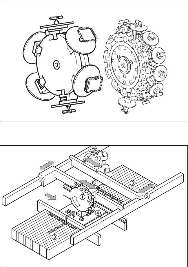
Placement Heads:
Head Modularity
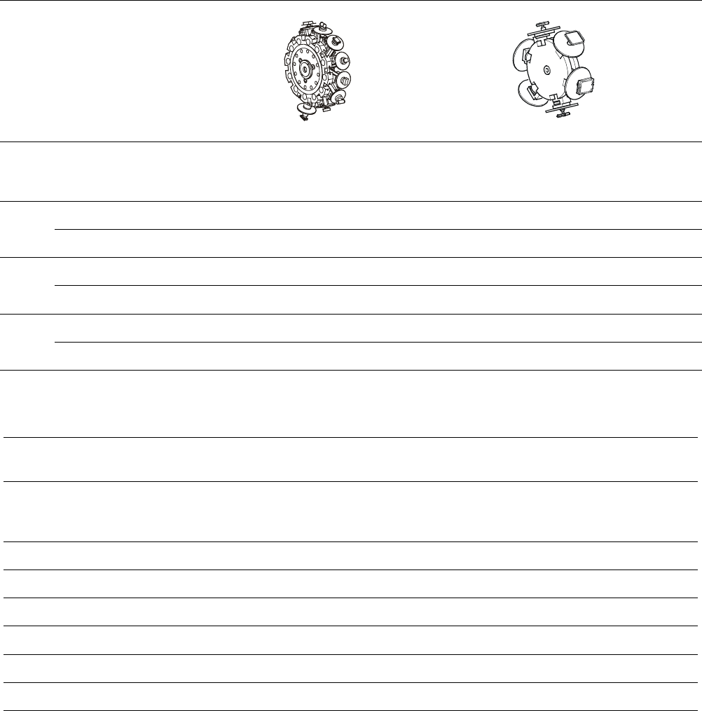
Placement Heads for SIPLACE S-25 HM
6-Nozzle
Collect & Place
Head
12-Nozzle
Collect & Place
Head
Placement Principle of SIPLACE S-25
HM
➀ 6-Nozzle or 12-Nozzle
Collect & Place Head
➁ X-/Y-Gantry System
➂ Fixed Component Supply
➃ Fixed PCB
6
Placement Heads:
Placement Accuracy
Component Range
Placement Accuracy
a
Placement Head
Placement Accuracy
12-Nozzle
Collect & Place Head
6-Nozzle
Collect & Place Head
X/Y Accuracy 67.5 µm 60 µm
3
Sigma
Rot.-Accuracy 0.525° 0.225°
X/Y Accuracy 90.0 µm 80.0 µm
4
Sigma
Rot.-Accuracy 0.700° 0.400°
X/Y Accuracy 135.0 µm 120.0 µm
6
Sigma
Rot.-Accuracy 1.050° 0.450°
a) As defined in “Scope of Service and Delivery SIPLACE”.
Component Range
12-Nozzle
Collect & Place Head
6-Nozzle
Collect & Place Head
Component size
0.6 x 0.3 mm
2
b
to
18.7 x 18.7 mm
2
1.6 x 0.8 mm
2
to
32 x 32 mm
2
Max. component height 6 mm 8.5 mm
Max. component weight 2 gr 5 gr
Placement force 2.4 - 5.0 N 2.4 - 5.0 N
Performance See table on page 3 See table on page 3
Min. pitch lead / bump 500 / 350 µm 500 / 560 µm
Min. ball / bump diam. 200 µm 320 µm
b) 0201 (recommended to order the special 0201-kit).
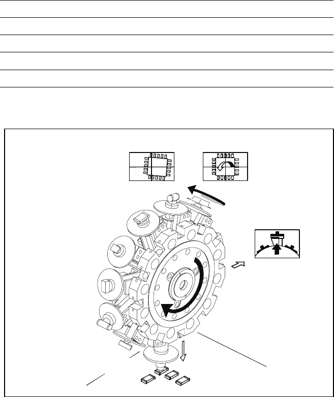
7
12-Nozzle Collect & Place Head for High Speed Placement
Component Pick-Up/
Placement
Segment
Removal
Point
Turning to
the Placement
Position
Component
Vision
Description
The 12-Nozzle placement head
operates on the Collect & Place
principle. In contrast to classic chip
shooters, the 12 vacuum nozzles
of the SIPLACE Collect & Place
head rotate around a horizontal
axis. This does not only save
space:
Due to the small diameter com-
pared to chip shooters, the cen-
trifugal forces are significantly
lower. The results are high-speed,
reliable placement and the same
cycle time for all components.
Components are picked up and
placed reliably with the aid of vac-
uum followed by a gentle air kiss.
A number of vacuum tests moni-
tors if the component has been
picked up and placed accurately.
Various control and self-learning
functions further enhance the de-
pendability of the system:
§ The optical recognition of feeder
positions records the exact posi-
tion of the feeder table.
§ A camera on the placement head
(component vision module) de-
termines the exact position of
each component on the nozzle.
§ For every feeder the pick-up
offsets are averaged over the
last ten pick-ups. This enables
the head to dial-in on the pre-
cise pick point for each compo-
nent.
§ In addition, the package form is
also checked. If the actual geo-
metric dimensions of the com-
ponent do not correspond to
those programmed, the compo-
nent is rejected.
§ Components rejected by the vi-
sion system are dumped into a
bin, reject feeder or matrix tray.
Any rejected component gets
automatically placed during a
repair run.
§ Warpage of the PCB is accom-
modated by sensor stop acti-
vated z-axis placement. The sys-
tem also keeps the last ten
positions of the z-axis at com-
ponent placement and uses the
average of these values to im-
prove the drive down and place
speed of the cycle.
Placement Heads:
12-Nozzle Collect & Place Head for High Speed
Component Placement
Technical Data
Component range See table on page 6
Stroke of Z-axis max. 16 mm
Programmable placement force 2.4 to 5.0 N
Benchmark placement rate 12,500 cph (see also table on page 3)
Placement accuracy See table on page 6