00197044-02_IM_706_1_DE_EN - 第46页
Station S oftware 706. 1 / Install ation Man ual Ausgabe 11/2012 E dit ion 46 7.3 SX1/SX2 (V2) P lac ement M achin e For the SX 1/SX2 (V2) placem ent m achine the f ollow ing windo w is d isplayed, in w hich the M an ual…
Station Software 706.1 / Installation Manual Ausgabe 11/2012 Edition
45
7.1 X-Series Placement Machines
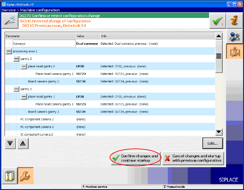
The following window is displayed for the X-series machines. Here you can edit, confirm or reject
the Auto-configuration.
Figure 7-5: Confirming Auto-configuration for X-series
► Click the Confirm changes and continue startup button to confirm the Auto-configuration.
► If the Coplan computer has been installed, you will additionally have to confirm or reject the 3-D
Coplan sensor.
7.2 X4Si Placement Machine
► When the X4Si placement machine is booted for the first time you have to select the following
options manually:
– If a TrayStak Feeder is used, this has to be defined for each location concerned in the
Auto-configuration.
– Table position (inner and outer)
Station Software 706.1 / Installation Manual Ausgabe 11/2012 Edition
46
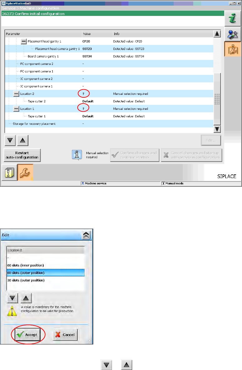
7.3 SX1/SX2 (V2) Placement Machine
For the SX1/SX2 (V2) placement machine the following window is displayed, in which the Manual
selection required note informs, that the table configuration has to be selected manually, as this is
not detected automatically.
Figure 7-6: Selecting table configuration
► Click the ? question mark next to Location 2.
The selectable table configurations are displayed.
Figure 7-7: Possible table configurations
► Select a table configuration with or .
Station Software 706.1 / Installation Manual Ausgabe 11/2012 Edition
47
► Click the Accept button.
► Repeat the steps for Location 1.
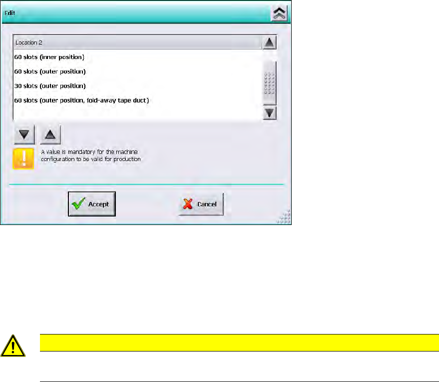
Settings for manual tray Carrier SX
If the manual tray Carrier SX is used, the insert frame with the fold-away tape guide channel is
required. This has to be set manually. In this case, the following selectable table configurations are
displayed:
Figure 7-8: Settings for manual tray Carrier SX
► Select the 60 slots (outer position, fold-away tape duct) table configuration.
► Click the Accept button.
Thus, the 27x27 reject bin and the left reject channel on the location are excluded from the
configuration.
CAUTION
If this setting is not made, the component may be rejected over the tray and the Z axis
may dash hard against the tray.
► Repeat the steps for Location 1.