00193431-03.pdf - 第40页
2 Assembly instructions Long Board Option SIPL ACE HS-50 HS-50 Modification Long Board Option 03/2007 Edition 40 2.1.3 Connector pin assignment s : Run the cables through the power chai n and cable duct s to the PCB tran…
HS-50 Modification Long Board Option 2 Assembly instructions Long Board Option SIPLACE HS-50
03/2007 Edition
39
2
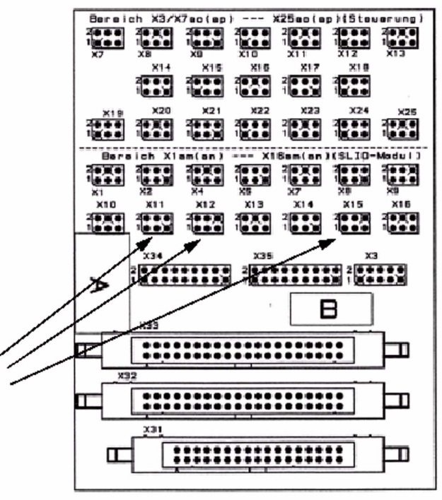
Fig. 2.12 - 3 Plan view of the distribution board plugs, board part no.: 00348267-01
2
: Close the cable ducts.
: Refit the lifting table.
: Fix the stopper BERO in its definitive position with a screw.
2
2
2
2
2
2
2
Connections
2 Assembly instructions Long Board Option SIPLACE HS-50 HS-50 Modification Long Board Option
03/2007 Edition
40
2.1.3 Connector pin assignments
: Run the cables through the power chain and cable ducts to the PCB transport controller board.
: Strip the individual wires back by approx. 3 mm.
: Crimp the contacts onto the individual wires and check the coding.
: Attach the plugs to the stripped cable ends as shown in the following photographs.
2
2
Views from above (cable side):
Valve actuator connection
Plug: X12
Cable length: 160 cm
Brown
White
Not used
(no coding)
Coding
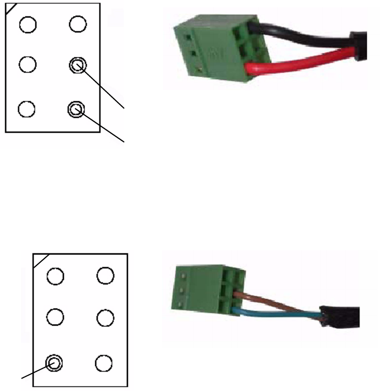
PCB stopper valve (BERO) connection
Plug: X11
Cable length: 200 cm
Brown
White
Coding
HS-50 Modification Long Board Option 2 Assembly instructions Long Board Option SIPLACE HS-50
03/2007 Edition
41
2
2
: Plug the cables in at the appropriate positions (see diagrams above and below).
: Close the protective covers.
: Switch the placement machine on at the main switch.
2
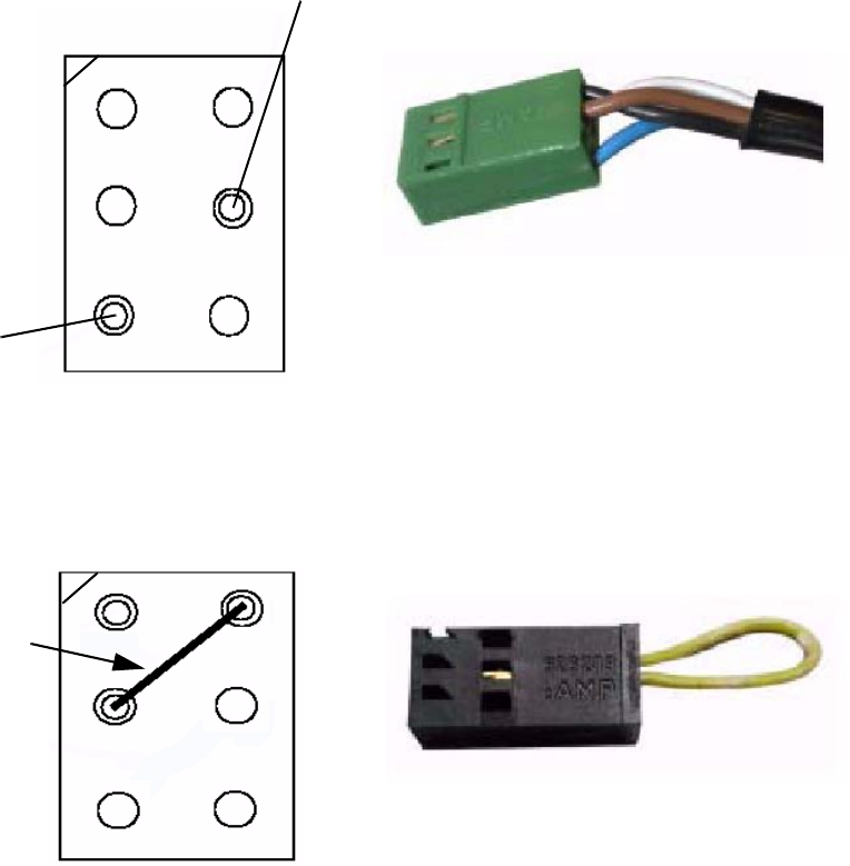
Light sensor WT4-2P330 connection
Plug: X16
cable length: 190 cm
White
Key
Coding plug: X19
Jumper
Brown
Black
Blue
Key