00192375-01.pdf - 第15页
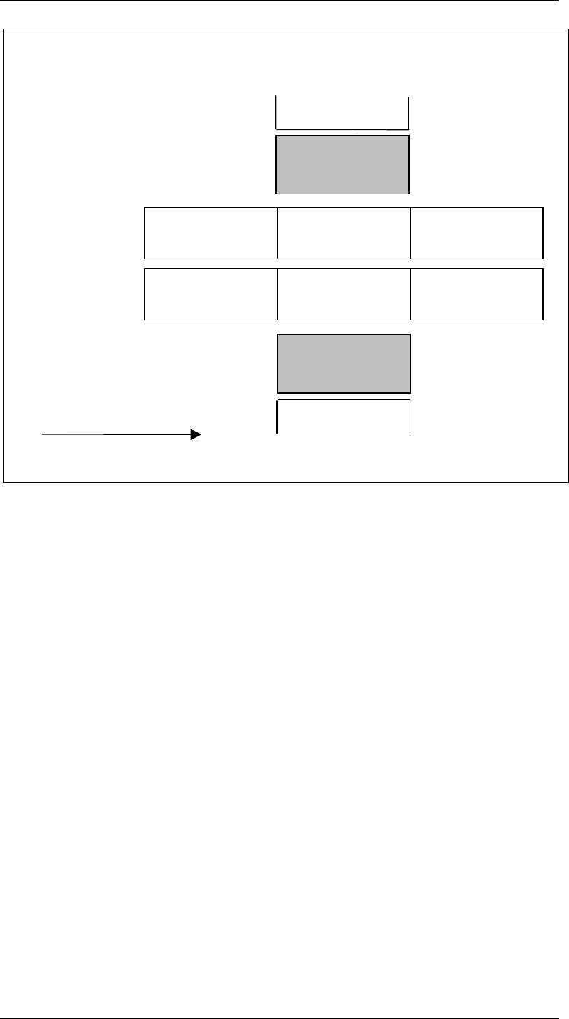
SIPLACE GEM for S25, HS50 SW Version GEM 502.01 HOST Inter face Manual ©Siemens AG, all rights reserved page 15 of 236 This illustration shows one S25 machine with an MTC. T here is just one feeder location on each side.…
SIPLACE GEM for S25, HS50 SW Version GEM 502.01
HOST Interface Manual
Page 14 of 236 ©Siemens AG, all rights reserved
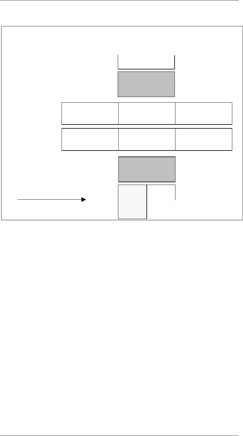
This figure shows an S25 machine with 1 MTC.
If the machine has only 1 MTC, there is one divided feeder location and one undivided
feeder location. The MTC can be on location 1 or 3.
If the MTC is on location 1, locations 1 and 2 are on the RH side and there is a shared
feeder location on the LH side (see illustration).
If the MTC is on the LH side, locations 3 (MTC) and 4 are on the LH side and a there is a
shared location 1 on the RH side.
TWIN-Input
conveyor
TWIN-First
Processing
conveyor
TWIN-Output
conveyor
Input
conveyor
First Processing
conveyor
Output
conveyor
Direction of transport
Conveyor 2 (left)
Conveyor 1 (right)
Gantry 1
Revolverhead 1
Gantry 2
Revolverhead 2
Location
3
Location
2
Location
1
07&
SIPLACE GEM for S25, HS50 SW Version GEM 502.01
HOST Interface Manual
©Siemens AG, all rights reserved page 15 of 236
This illustration shows one S25 machine with an MTC. There is just one feeder location on
each side.
6WDWH'LDJUDPV
This document uses several )LQLWH6WDWH0DFKLQH diagrams to describe the current
condition of the Equipment’s SECS link, material handling mechanisms, and process
cycle. Each Finite State Machine diagram includes a State Diagram and a complete
description of the states and state transitions.
All Finite State Diagrams have been prepared in the format specified in the GEM
standard. This notation is required as a fundamental part of GEM compliance and must
be included in the Equipment SECS Interface Documentation. This notation is the
„Statechart“ notation developed by David Harel.
The following are the major characteristics of this notation as it is used in this document:
Each state is represented by a rectangle with rounded corners.
A collection of sub-states may be grouped into a super-state.
The entity described by the diagrams will be in one and only one of the sub-states at all
times.
Variables representing the current state of an entity do not contain values for super-
states, only the lowest sub-state is represented.
State transitions are represented by single-headed arrows.
Each state transition is a Collection Event, and it has a unique Collection Event ID (CEID)
TWIN-Input
conveyor
TWIN-First
Processing
conveyor
TWIN-Output
conveyor
Input
conveyor
First Processing
conveyor
Output
conveyor
Direction of transport
Conveyor 2 (left)
Conveyor 1 (right)
Gantry 1
Revolverhead 1
Gantry 2
Revolverhead 2
Location
3
Location
1

SIPLACE GEM for S25, HS50 SW Version GEM 502.01
HOST Interface Manual
Page 16 of 236 ©Siemens AG, all rights reserved
An arrow directly from a super-state to another state describes a Collection Event that can
occur while the entity is in any one of the sub-states contained in the super-state.
An arrow directly into a super-state to the + (history) symbol describes a transition to the
lowest sub-state which described the entity just before the transition out of the super-
state.
An arrow directly into a super-state to the & (conditional) symbol describes a transition to
a particular sub-state based on some other relevant data. The conditional data is not
represented in the diagram but is described in the associated text.