00194440-10_SM_X-Series_Customer_en.pdf - 第84页
Service Work Gantries 3.3.1 Replacing the X Axis Incremental Encode r 84 Service Manual SIPLACE X Series 3.3 3 . 3 G a n t r ie s Gantries 3.3.1 3 . 3 . 1 R e p la c in g t h e X A x is I n c r e m e n t a l E n c o d e …
Service Work
3.2.3 Valve Block Connections Pneumatic
Service Manual SIPLACE X Series 83
3.2.3.3
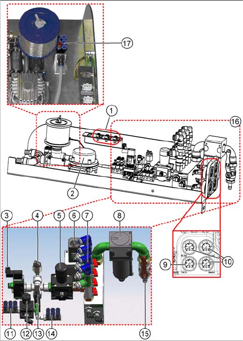
3.2.3.3 Pneumatic unit - version 3 [03060279-xx]
Pneumatic unit - version 3 [03060279-xx]
The pneumatic unit (X4i) [03061118-xx] is structurally identical with the [03060279-xx]. This pneumatic
unit is used in all X and HF series SIPLACE machines.
1. Power supply
Proportional valve [03038685-xx],
Pneumatic main valve [03038687-xx] and
Safety valve [03038686-xx]
2. Fan unit with motor generating compressed air
[03004094-xx],
Air intake filter [00376006-xx] and
Upstream series electronics [03006517-xx]
3. 5/2 Solenoid valve [00344974-xx]
4. Pressure switch 1-10 bar [03038425-xx]
5. Pressure regulator [03062103-xx]
6. Pressure regulator [03038725-xx]
7. Shutoff valves for gantries
8. Air filter with container [03038691-xx]
9. Manometer 0-10 bar [03062195-xx]
10. Manometer 0-6 bar [03062197-xx]
11. 2.5 bar connections for NC C&P6/12 or bulkcase
12. Pressure regulator [03028263-xx]
13. 5/2 way valve [03062277-xx]
14. 5 bar connections for docking unit or NC C&P20
15. Connection for inlet pressure (5 to 10 bar)
16. Control block [03062079-xx]
17. Distributor for cutters and conveyor
Service Work
Gantries 3.3.1 Replacing the X Axis Incremental Encoder
84 Service Manual SIPLACE X Series
3.3
3.3 Gantries
Gantries
3.3.1
3.3.1 Replacing the X Axis Incremental Encoder
Replacing the X Axis Incremental Encoder
Parts, equipment and tools
▪ Read head MS22.74 X/Y 677mm [03090201-xx] (replaces: [03020588-xx])
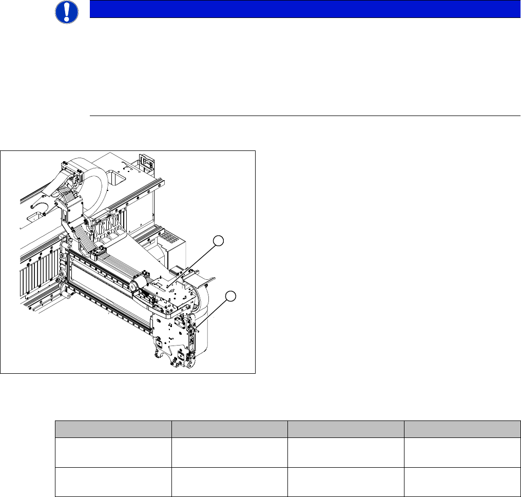
Overview
Press-fit connections
NOTICE
Head interface
The new read head for the X axis "Read head MS22.74 X/Y 677 mm [03090201-xx] may only
be fitted with a "head interface" from FS06 [03000901-06] or a "mirrored head interface" from
FS03 [03029048-03].
The read head can only be fitted together with the new "Tape measure X axis SX4" [03092558-
xx]. If an old read head is upgraded to the new version MS22, you will also need to replace the
scale.
1. Installation point for head interface and Vision board
2. Incremental encoder position
► Unplug the incremental encoder press-fit connection
(2) from the head interface (1).
1
2
Assembly Gantry Board Terminals
X axis incremental en-
coder
Gantry 1 (C&P head ) Head interface
[03000901-xx]
X15ac
X axis incremental en-
coder
Gantry 2 (TwinHead) Head interface
[03000901-xx]
X15bc
Service Work
3.3.1 Replacing the X Axis Incremental Encoder Gantries
Service Manual SIPLACE X Series 85
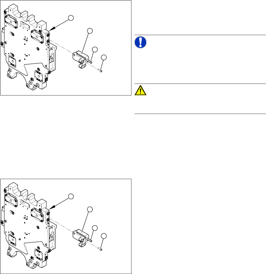
Removal
Installation
1. Head plate - front view
2. Incremental encoder
3. Three fastening screws
4. Grub screw (secured with Loctite No. 241)
NOTICE!
Grub screw on the incremental encoder
If the incremental encoder is installed on the head plate
of a CFK 04 or 06 gantry, the grub screw is without func-
tion. Do not loosen or tighten this grub screw.
CAUTION!
HF – CFK02 gantry
Refer to the relevant guide for the CFK02 gantry.
► Unthread the connection cable as far as the incre-
mental encoder (2).
► Loosen the three screws (3) fastening the incremen-
tal encoder (2) of the X axis and carefully lift off the
incremental encoder.
3
4
1
2
► Clean the reading surface of the incremental encoder
with a cloth and ethanol or with a cleansing tip.
► Loosely fasten the incremental encoder (2) with three
fastening screws (3).
► The incremental encoder must be aligned with a
0.75 mm gap (for the old read head [03020588-xx]
0.4 mm) to the scale. Use the corresponding thick-
ness gauge (plastic).
3
4
1
2