00194440-10_SM_X-Series_Customer_en.pdf - 第115页
Service Work 3.3.8 Replacing the Trailing Cable Gantries Service Manual SIPLACE X Series 115 Version 2 after B-079 See also 3.3.8.7.2 Preparing th e Trailing Cable [ ➙ 112] 3.3.8.4 Handling the Hose Unlocking To …
Service Work
Gantries 3.3.8 Replacing the Trailing Cable
114 Service Manual SIPLACE X Series
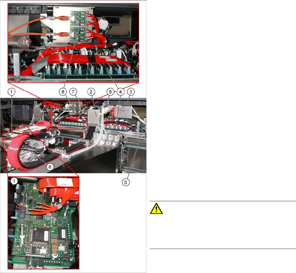
Overview
Version 1 from B-079
1. Head board with digital Vision board assembly
[03017836-xx]
2. Trailing cable console
3. Power track chain
4. Trailing unit interface gantry
5. Pneumatic hoses to the pneumatic distributor (in the
machine base)
6. Gantry distributor
7. Gantry Interface
8. Hotlink filter [03010670-xx]
9. Connection piece for cooling tubes to Y motor
► The flat ribbon cable and the camera cable are run
from the head board (1) via the trailing cable console
(2) and the power track chain (3) to the gantry inter-
face (7) and the trailing cable interface gantry (4).
The camera cable ends at the hotlink board (8).
► The pneumatic hoses are fed from the pneumatic dis-
tributor (6), via the trailing cable console (2) and the
power track chain (3) to the gantry distributor in the
machine base.
► Disconnect the camera cable from the hotlink board
(8).
► Remove cable ties where necessary.
CAUTION!
Note the order in which the terminal connections are ar-
ranged.
Label the press-fit connections to the flat ribbon cable
and the camera cable, for easier reconnection later.
► Disconnect the Y motor cooling tubes at the connec-
tion pieces (9).
Service Work
3.3.8 Replacing the Trailing Cable Gantries
Service Manual SIPLACE X Series 115
Version 2 after B-079
See also
3.3.8.7.2 Preparing the Trailing Cable [ ➙ 112]
3.3.8.4 Handling the Hose Unlocking Tool [03047090-xx] [ ➙ 99]
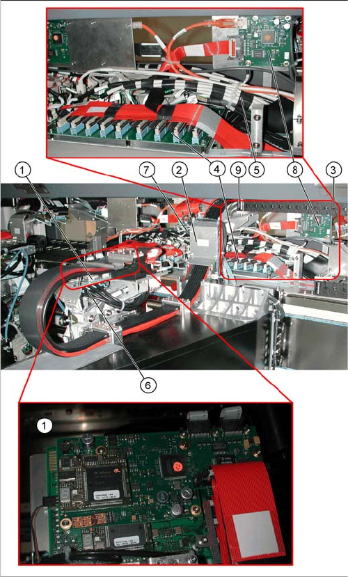
1. Vision board spread spectrum (VBSX) assembly
[03054634-xx]
2. Trailing cable console
3. Power track chain
4. Trailing unit interface gantry
5. Pneumatic hoses to the pneumatic distributor (in the
machine base)
6. Gantry distributor
7. Gantry Interface
8. Vision hotlink adapter VHA assembly [03054633-xx]
9. Connection piece for cooling tubes to Y motor
Service Work
Gantries 3.3.8 Replacing the Trailing Cable
116 Service Manual SIPLACE X Series
Removal
► Loosen the flat ribbon cable on the trailing cable interface gantry (1). Take care not to lose the brack-
ets for the press-fit connections. They could fall out and be lost.
► Remove cable ties where necessary.
► Remove the necessary cable ties at the gantry interface (4) and disconnect the flat ribbon cable.
► Disconnect the motor, proximity switches, incremental encoder and temperature sensor cables from
the gantry interface (4).
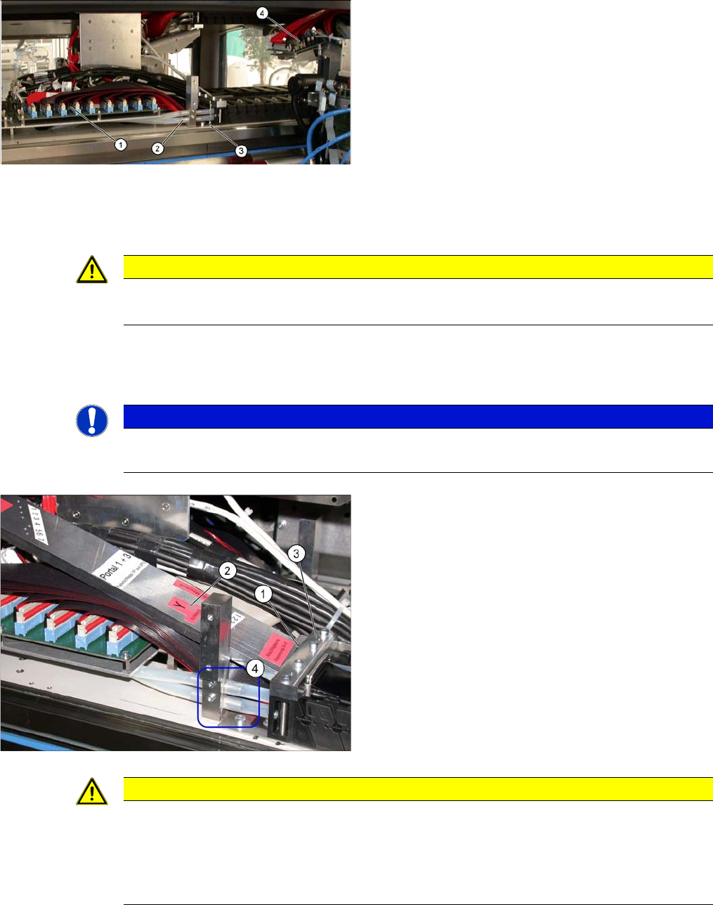
1. Trailing unit interface gantry
2. Pneumatic for vacuum pump (option)
3. Mount for trailing cable
4. Gantry Interface
CAUTION
Note the order in which the terminal connections are arranged.
► Label the press-fit connections to the flat ribbon cables, for easier reconnection later.
NOTICE
Refitting the gantry interface board.
The gantry interface board is installed on the mount of the new trailing cable.
To sever the pneumatic hoses, which lead to the pneu-
matic distributor inside the machine base, proceed as fol-
lows:
► Place the gauge (1) on the mount (3).
► Use the gauge to label the hoses at the Y hose mark
(2).
CAUTION
Before cutting the pneumatic hoses
► Label the order of pneumatic hoses (from 1 to 7 – inside to outside). This is important to
ensure that the hoses are then correctly connected again after cutting.
► During cutting, make sure that the pneumatic hoses do not fall into the machine base. Se-
cure them accordingly.