00194440-10_SM_X-Series_Customer_en.pdf - 第133页
Service Work 3.4.4 Replacing the DLM Head Placement heads Service Manual SIPLACE X Series 133 3.4.4 3 . 4 . 4 R e p la c in g t h e D L M H e a d Replacing the DLM Head Overview Removal 1. Illumination control 2. Vacuum …
Service Work
Placement heads 3.4.3 Replacing the Twin Head [03001095Sxx]
132 Service Manual SIPLACE X Series
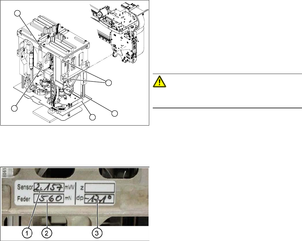
Entering the force values for the new module
► Loosen the screws (1) fastening the cover (3).
► Loosen the four M4x14 fastening screws (2) with a
long Allen key.
► Pull the module out of the locating pins.
► Make a note of the force values for the new module.
These force values can be found on a label at the side
of the module.
► Fit the new module.
CAUTION!
Observe the torque
Tighten the M4x14 screws with a torque of 2.7 Nm.
► Reconnect the system to the electrical and com-
pressed air systems.
► Fit the cover (3).
2
2
1
3
2
► Start the SITEST program and enter the new force
values for this module.
► To do this, select the TwinHead axis function in the
SITEST program and activate the appropriate seg-
ment (module).
► Activate the Z axis radio button and select the Param-
eter... button.
► Enter the values for the force sensor adjust value and
the spring bias.
► Use the SITEST program to calibrate the TwinHead.
⇨ Head height
⇨ Camera IC
⇨ Head calibration
Service Work
3.4.4 Replacing the DLM Head Placement heads
Service Manual SIPLACE X Series 133
3.4.4
3.4.4 Replacing the DLM Head
Replacing the DLM Head
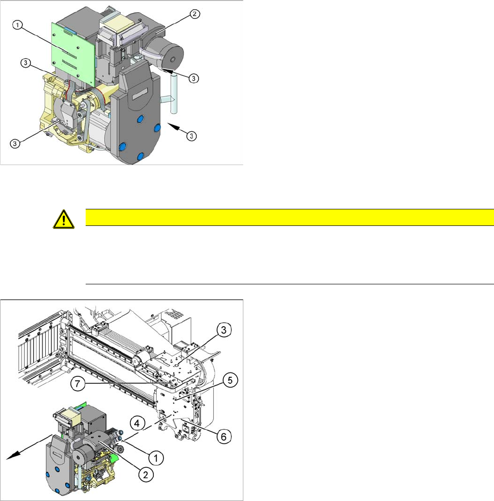
Overview
Removal
1. Illumination control
2. Vacuum generator
3. Four fastening screws M4x18
Article numbers
▪ C&P head DLM3 with twelve segments [03041228-
xx] (C&P12 head)
▪ DLM3 head with six segments [03041229-xx] (C&P6
head)
CAUTION
Do not place the head down on the valve positioning drives!
The valve positioning drives of the star can be misaligned under mechanical loads.
► After removal, place the head carefully down on a soft surface, without putting pressure on
the valve positioning drives.
► Remove the compressed air hoses (1) from the pneu-
matic coupling of the vacuum generator (2).
► At the head, unplug the press-fit connections to the
head interface (3) and head adapter (7).
► Loosen the four M4x18 screws (4) fastening the
head.
► Carefully pull the head off the parallel pins (5) on the
head plate (6) and remove the head from the ma-
chine.
► Place the head carefully down on a soft surface, with-
out putting pressure on the valve positioning drives.
Service Work
Placement heads 3.4.5 Replacing the C&P20A Head
134 Service Manual SIPLACE X Series
Installation
3.4.5
3.4.5 Replacing the C&P20A Head
Replacing the C&P20A Head
Parts, equipment and tools
▪ C&P20A head incl. camera [03062095-xx]
▪ C&P20A head without camera [03058420-xx]
▪ Torque screwdriver 100-500 Ncm [03078400-xx]
▪ Extension/straight TX20 [03073256-xx]
▪ Bit holder for Torque Vario-S screwdriver [03078706-xx]
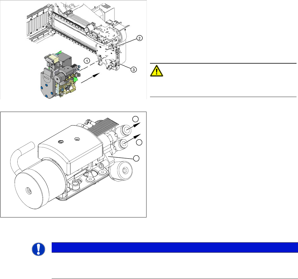
► Carefully move the head towards the head plate (3).
► Make sure that the parallel pins (2) on the head plate
slide into the holes drilled into the back part of the
head.
► Carefully push the head towards the head plate until
it lies flat against it.
► Fix the head with the four screws provided (1).
CAUTION!
Observe the torque
Tighten the screws with a torque of 2.7 Nm.
► Connect the compressed air hoses (1) to the pneu-
matic coupling on the vacuum generator (2).
► Reconnect to the electricity system.
► Use the SITEST program to calibrate the head.
1
1
2
NOTICE
Fast Head Exchange (FHE)
► Observe the instructions in section "3.4.1 Fast Head Exchange" [➙122] when exchanging
a head.