00194440-10_SM_X-Series_Customer_en.pdf - 第14页
Introduction Safety Instructions 1.1.8 Laser Classification 14 Service Manual SIPLACE X Series 1.1.8 1 . 1 . 8 L a s e r C la s s if ic a t io n Laser Classification 1.1.8.1 1 . 1 . 8 . 1 L a s e r C la s s 1 Laser Class…

Introduction
1.1.4 Safety Instructions for the Compressed Air Supply Safety Instructions
Service Manual SIPLACE X Series 13
1.1.4
1.1.4 Safety Instructions for the Compressed Air Supply
Safety Instructions for the Compressed Air Supply
1.1.5
1.1.5 Safety Instructions for Work on the Cutting Device
Safety Instructions for Work on the Cutting Device
1.1.6
1.1.6 Safety Instructions for the Gantry
Safety Instructions for the Gantry
1.1.7
1.1.7 Safety Instructions on Hazardous Materials
Safety Instructions on Hazardous Materials
CAUTION
Risk of injury from compressed air!
Risk of injury when disconnecting the compressed air lines.
► NEVER disconnect compressed air lines while they are still pressurized.
CAUTION
Prolonged interruptions to the compressed air supply can cause damage.
When the machine is switched on, do not use the shutoff valve to interrupt the compressed air
supply for more than 30 minutes.
► If you need to shut off the compressed air system for longer in order to carry out your work,
you must switch the placement system off at the main switch and disconnect it from the
power supply.
WARNING
Risk of injury when working near the cutter.
If you wish to work on the tape cutter, disconnect the machine from the mains supply and com-
pressed air supply.
► Wait until the operating pressure has dropped to 0 MPa.
► Always secure the machine against unauthorized reactivation.
CAUTION
Risk of injury when performing service work on the cutter.
Never support the cutter on your body, e.g., on your knees or thighs. Do not place your feet
under the cutter.
► Wear appropriately thick protective gloves.
► When removing/fitting the cutter, hold it only on the left and right, on the outside.
CAUTION
Moving the gantry can damage the placement head.
When moving the gantry, observe the following:
► NEVER move the gantry by pushing with your hands against the placement head.
► NEVER push the gantry while the Z axis is lowered.
CAUTION
Observe the safety data sheets
Observe the applicable safety data sheet, when handling hazardous materials (e. g. Loctite
241, ethanol).
Introduction
Safety Instructions 1.1.8 Laser Classification
14 Service Manual SIPLACE X Series
1.1.8
1.1.8 Laser Classification
Laser Classification
1.1.8.1
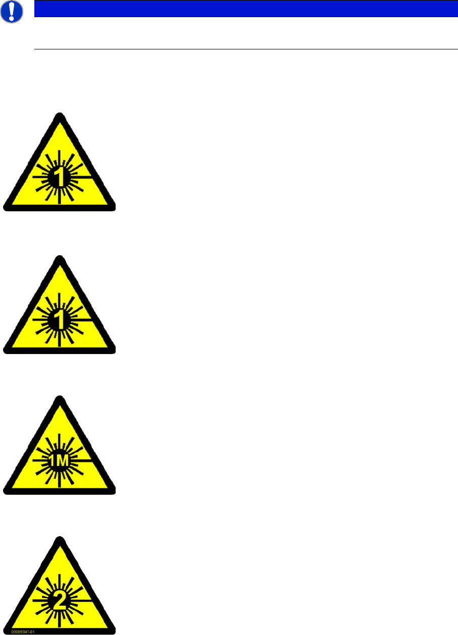
1.1.8.1 Laser Class 1
Laser Class 1
Classification of the Whole Machine
Classification of the Camera Systems
1.1.8.2
1.1.8.2 Laser Class 1M
Laser Class 1M
1.1.8.3
1.1.8.3 Laser class 2
Laser class 2
NOTICE
Laser class 1 and 1M
Modules in laser classes 1 and 1M are not labeled.
All installed camera systems and the whole machine (when ready for oper-
ation) are assigned to laser class 1.
The laser classes are determined according to DIN EN 60825-1:2001.
The following camera systems are assigned to laser class 1:
▪ Stationary component cameras for the SIPLACE TwinStar (TwinHead)
and the SIPLACE Multistar (CPP)
▪ Component camera, stationary, P&P, type 33, 55 x 45, digital
▪ Component camera, stationary, P&P, type 25, 16 x 16, digital
▪ Component camera, stationary, P&P, type 36, 32 x 32, digital
Do not look directly at this with optical instruments!
The following camera systems are assigned to laser class 1M:
▪ CO camera C&P, type 23, 6 x 6 on the SpeedStar
▪ CO camera C&P, type 41, 6 x 6 on the SpeedStar
▪ CO camera C&P, type 30, 27 x 27 on the MultiStar
▪ CO camera C&P, type 30, 18 x 18 on the 12-segment Collect&Place
head
Laser radiation
Do not look into beam!
The following modules are assigned to laser class 2:
▪ PCB barcode scanner
▪ Component sensor on the SpeedStar
▪ Component sensor on the MultiStar
The entire machine is classified as laser class 2 if the coplanarity laser mod-
ule option is installed.
Introduction
1.1.8 Laser Classification Preparatory Work...
Service Manual SIPLACE X Series 15
1.2
1.2 Preparatory Work...
Preparatory Work...
Purpose and Scope
Before performing any preventive maintenance work, conversion work or service work, a procedure of
locking and tagging must be followed and warning signs must be attached if not stated otherwise. If it is
not necessary to switch off the machine, it is explicitly mentioned.
The procedure, when followed correctly, eliminates the possibility of an employee being injured.
Description
Whenever it becomes necessary to isolate, control and release energy, the following procedure is to be
followed.
► Notify affected employees.
► Switch off the machine and all additional devices. Carry out all normal stopping procedures:
⇨ Press the STOP button.
⇨ Shut down the station computer.
⇨ Switch the machine off at the main switch.
► Isolate the machine from all its energy sources:
⇨ Shut off the compressed air supply.
⇨ Shut off the main power supply.
► Lock out the machine.
⇨ Attach a lock wherever possible (e.g. to the main power switch or the motor contactor).
NOTICE
Additional safety measures
These procedures represent the minimum lock/tag out requirements for the machine during
preventive maintenance work and service work. Any additional safeguards needed to complete
work safely can be specified by facilities supervision, the safety officer, the safety committee
and the health department.
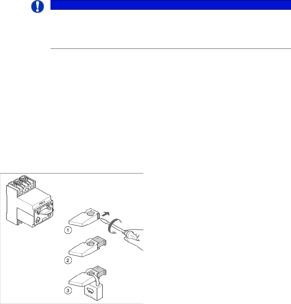
Example: attaching a padlock to the motor contactor
► Turn the operating lever (1) counterclockwise.
► Use the screwdriver to push the locking lug (2) out of
the operating lever (1).
► Secure the operating lever with a padlock (3).