00194440-10_SM_X-Series_Customer_en.pdf - 第141页
Service Work 3.4.7 Replacing Stationary Co mponent Camera Digital Type 25/33/ 36 Placement heads Service Manual SIPLACE X Series 141 3.4.7.1 3 . 4 . 7 . 1 I n s t a lla t io n H e ig h t o f t h e S t a t io n a r y C a …
Service Work
Placement heads 3.4.7 Replacing Stationary Component Camera Digital Type 25/33/36
140 Service Manual SIPLACE X Series
3.4.6.4
3.4.6.4 Running the Valve Positioning Drive Cables
Running the Valve Positioning Drive Cables
3.4.7
3.4.7 Replacing Stationary Component Camera Digital Type 25/33/36
Replacing Stationary Component Camera Digital Type 25/33/36
Refer to the appropriate assembly instructions:
X series, SX series, D3 and D1:
▪ Assembly Instructions Stationary Camera 25 (FC) [00194554-xx] (German and English)
▪ Assembly Instructions Stationary Camera Type 33/36 (IC) [00196608-xx] (German and English)
X Series S:
▪ Assembly Instructions Stationary Camera type 25/33 [00197397-xx] (German and English)
See also
3.7.1 Replacing the X-Series COT Insert [03015680-xx] [ ➙ 195]
5.6.6 DIP Switch for Camera Types 25 and 33 [ ➙ 357]
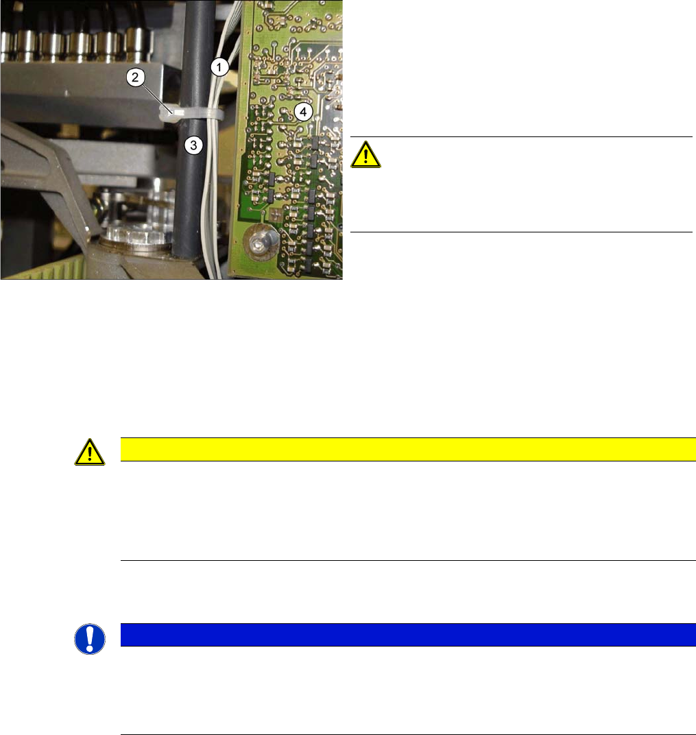
Avoid loose cables.
The diagram shows the board support to the side of the
placement head and the illumination board (4) on the
component camera.
The connection cables for the valve positioning drives (1)
of the reject and placement circuits need to be fixed at the
bolt of the board holder (3) with a cable tie (2).
CAUTION!
Wrap insulating tape around bare bolts
If the bolts are not already covered with a plastic hose, as
shown here, wrap insulating tape around the fixture point.
CAUTION
Risk of injury with cameras of type 25
A heavy mark caul is mounted with the same fixture screws for cameras of type 25. This mark
caul is otherwise only held by the locating pins. If this mark caul falls down, it could cause inju-
ries.
► Make sure that this mark caul is not pulled off the locating pins.
NOTICE
Camera adaptor
You may need to fit an IC camera adaptor assembly. (See the assembly instructions)
► Location 1 to 3: IC camera adaptor assembly SX4a [03099054-xx]
► Location 4: IC camera adaptor assembly SP4 SX4a [03099004-xx]
Service Work
3.4.7 Replacing Stationary Component Camera Digital Type 25/33/36 Placement heads
Service Manual SIPLACE X Series 141
3.4.7.1
3.4.7.1 Installation Height of the Stationary Camera
Installation Height of the Stationary Camera
The installation height at which the camera can be installed depends on the camera version. You will
either only be able to use one specific height or will have the option of several installation heights. The
following description only applies for the following camera versions with three possible installation
heights:
▪ Stationary component camera P&P (type 33) 55x45 digit. [03016339-xx] from version -06
▪ Stationary component camera P&P (type 36) 32x32 digit. [03042491-xx] from version -04
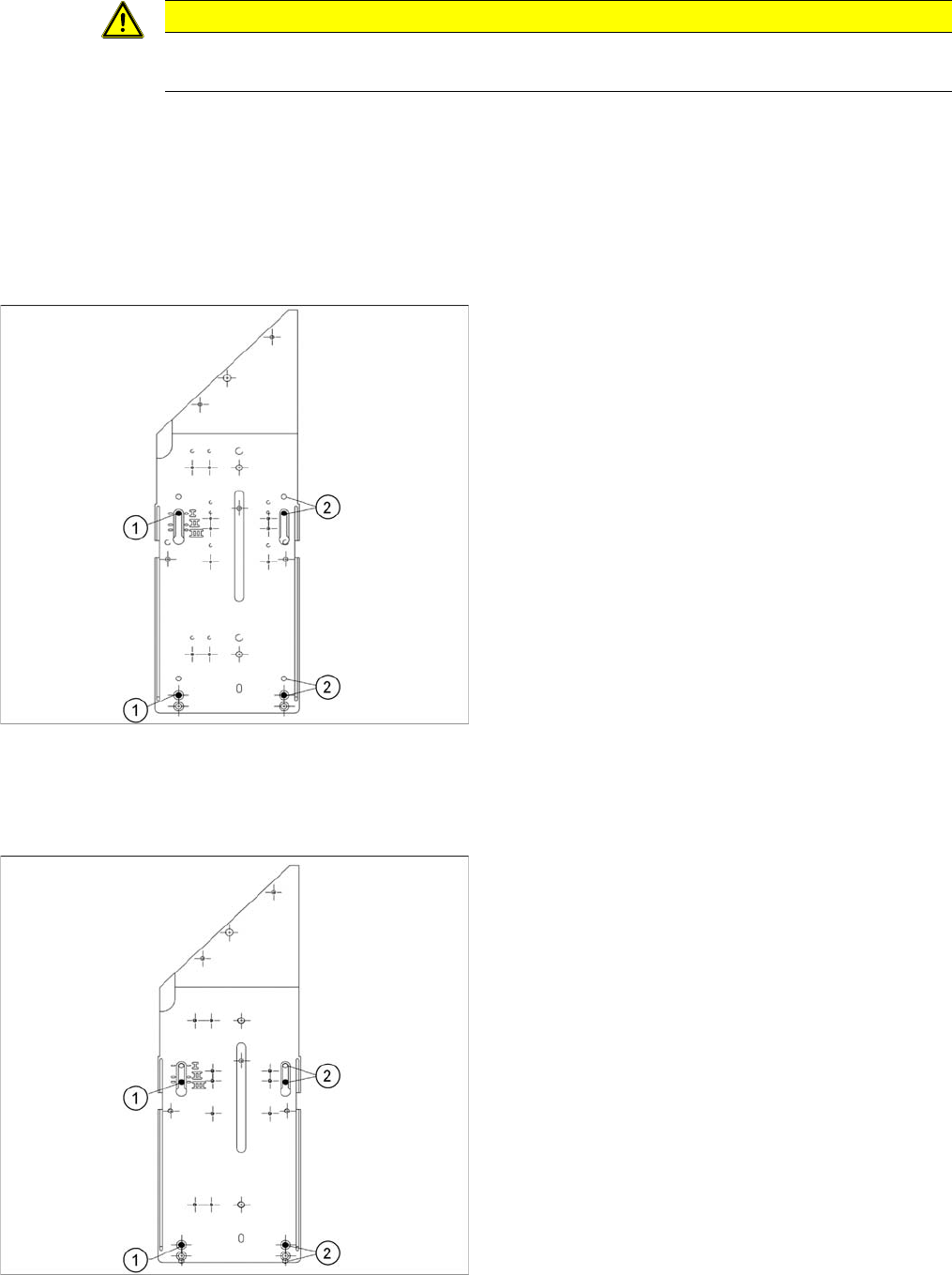
Stationary Camera in Position 1
Stationary Camera in Position 2
Position 2 is not relevant for the SX and the X series.
Stationary Camera in Position 3
CAUTION
Head crash danger
An incorrect installation height can result in a head crash!
1. Screw
2. Thread in the machine frame
Position 1 has to be used in the following cases:
▪ SX1/SX2: always
▪ SX4, X series: If at least one DLM or CPP head is
used in the corresponding placement area.
1. Screw
2. Thread in the machine frame
Position 3 has to be used in the following cases:
▪ SX1/SX2: never.
▪ SX4, X series: If only TwinHeads are used in the cor-
responding placement area.
Service Work
C&P20 Nozzle Changer 3.5.1 Replacing the Nozzle Changer
142 Service Manual SIPLACE X Series
3.5
3.5 C&P20 Nozzle Changer
C&P20 Nozzle Changer
Overview
3.5.1
3.5.1 Replacing the Nozzle Changer
Replacing the Nozzle Changer
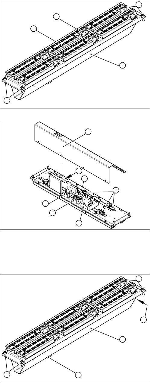
Overview
1. Cover (covering complete electronic and pneumatic
systems)
2. Toggle (six of them)
3. Nozzle magazine
4. Fastening screws
1. Cover (two x four fastening screws)
2. 1 wire board (NC control board)
3. Valve assembly
4. Swivel drive
5. Microswitch (six of them)
6. Green LED three mm
4
1
4
3
2
5
1
6
5
4
3
2
1. Cover (covering complete electronic and pneumatic
systems)
2. Connection plug
3. Compressed air connection
4. Fastening screws
4
1
4
3
2