00194440-10_SM_X-Series_Customer_en.pdf - 第143页
Service Work 3.5.1 Replacing the Nozzle Changer C&P20 Nozzle Changer Service Manual SIPLACE X Series 143 Removal Installation ► Unp lug the noz zle cha nger connection plug (2) . ► Disconnect the hose (3 ) from the p…
Service Work
C&P20 Nozzle Changer 3.5.1 Replacing the Nozzle Changer
142 Service Manual SIPLACE X Series
3.5
3.5 C&P20 Nozzle Changer
C&P20 Nozzle Changer
Overview
3.5.1
3.5.1 Replacing the Nozzle Changer
Replacing the Nozzle Changer
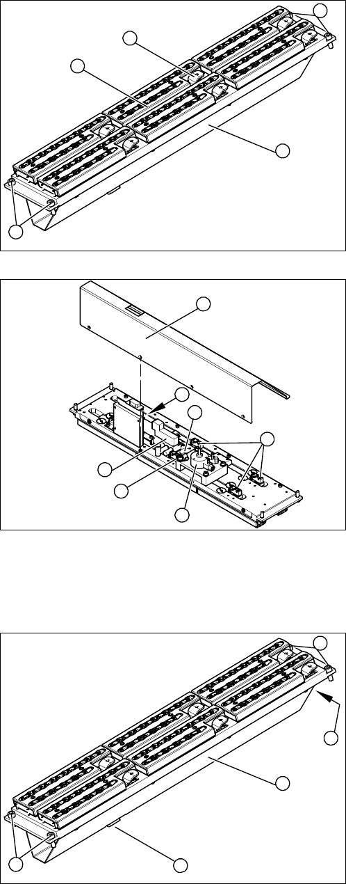
Overview
1. Cover (covering complete electronic and pneumatic
systems)
2. Toggle (six of them)
3. Nozzle magazine
4. Fastening screws
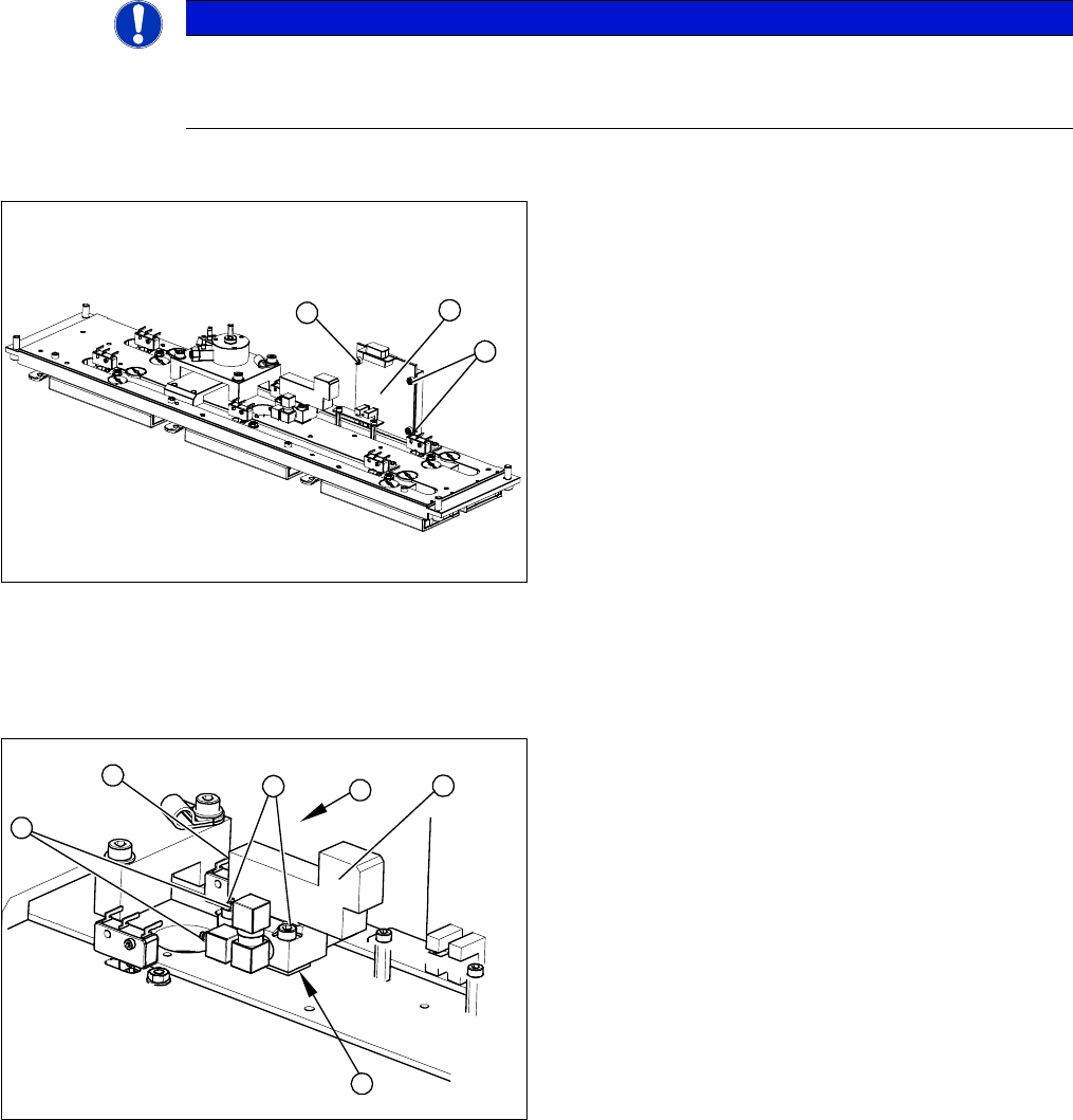
1. Cover (two x four fastening screws)
2. 1 wire board (NC control board)
3. Valve assembly
4. Swivel drive
5. Microswitch (six of them)
6. Green LED three mm
4
1
4
3
2
5
1
6
5
4
3
2
1. Cover (covering complete electronic and pneumatic
systems)
2. Connection plug
3. Compressed air connection
4. Fastening screws
4
1
4
3
2
Service Work
3.5.1 Replacing the Nozzle Changer C&P20 Nozzle Changer
Service Manual SIPLACE X Series 143
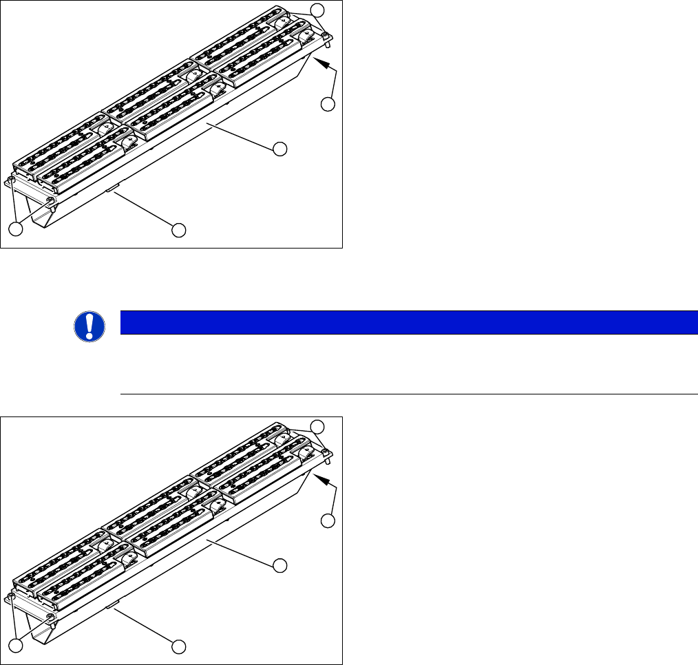
Removal
Installation
► Unplug the nozzle changer connection plug (2).
► Disconnect the hose (3) from the pneumatic coupling.
► Loosen the four fastening screws (4) and carefully lift
the nozzle changer out of the machine.
Pay attention to the support plates. Remember their
exact positions, as they will need to be returned to
these original positions, during assembly.
4
1
4
3
2
NOTICE
Fitting the nozzle changer
When fitting the nozzle changer, make sure that the component reject tray can be removed.
Make sure that the screws you are using are not too long, as these might jam the reject tray.
► Fit the new nozzle changer with the support plates.
► Reconnect to the electrical and compressed air sys-
tems.
► Check the mechanical height of the nozzle changer
(see Setting the Nozzle Changer Height).
4
1
4
3
2
Service Work
C&P20 Nozzle Changer 3.5.2 Replacing the Board for the 1 Wire NC [03015388-xx]
144 Service Manual SIPLACE X Series
3.5.2
3.5.2 Replacing the Board for the 1 Wire NC [03015388-xx]
Replacing the Board for the 1 Wire NC [03015388-xx]
Removal/installation
3.5.3
3.5.3 Replacing the Complete Valve [03016830-xx]
Replacing the Complete Valve [03016830-xx]
Removal/Installation
NOTICE
New version [03015388-xx] is backwards compatible
Compared to the older version [03045735-xx], the new board is only equipped with an addition-
al interface for the CAN node assembly [03052927-01].
1. 1 wire board
2. 3 x fastening screws
► Label all connectors and leads connected to the 1
wire board (1).
► Unplug all connectors and leads from the 1 wire
board (1).
► Loosen the three screws (2) fastening the 1 wire
board (1).
► Install the new 1 wire board (1) and reconnect all
electrical leads.
► Fasten loose leads with cable ties.
2
1
2
1. Valve assembly
2. 2 x fastening screws
3. 3 compressed air connections
4. Electrical connection
► Unplug the three compressed air connections (3)
from the valve.
► Disconnect from the power supply (4).
► Loosen the two fastening screws (2).
► Remove the valve (1).
⇨ Take care not to lose the shim (5). This needs to
be replaced in the correct position again, during
assembly.
► Install the valve (1) and reconnect the power (4) and
compressed (3) air supplies.
► Attach the cover and return the nozzle changer to the
machine.
4
3
3
5
1
2