00194440-10_SM_X-Series_Customer_en.pdf - 第153页
Service Work 3.6.2 Replacing the Complete Drive Unit [00359284-xx] Modular PC B Conveyor System Service Manual SIPLACE X Series 153 Removal ► Switch off the machine and secure it to prevent unauthorized reactivation. ► P…
Service Work
Modular PCB Conveyor System 3.6.1 Manual Adjustment of Conveyor Edges
152 Service Manual SIPLACE X Series
3.6
3.6 Modular PCB Conveyor System
Modular PCB Conveyor System
3.6.1
3.6.1 Manual Adjustment of Conveyor Edges
Manual Adjustment of Conveyor Edges
Loosen the conveyor edges.
Restoring the clamp
► Push the conveyor edges back into their approximate starting position.
► Restore the clamping function by screwing the screws back into the clamps.
► Use the software to move the conveyor edges to their original position.
3.6.2
3.6.2 Replacing the Complete Drive Unit [00359284-xx]
Replacing the Complete Drive Unit [00359284-xx]
Overview
In some cases, it may be necessary to adjust the convey-
or edges manually (e.g. if the conveyor conversion board
should fail or if the lifting table unit is dismantled). In this
case, proceed as follows:
CAUTION!
After completing this task, move the conveyor sides back
to their approximate starting positions.
To enable you to find the starting positions later on, you
may want to mark the current positions of the conveyor
sides.
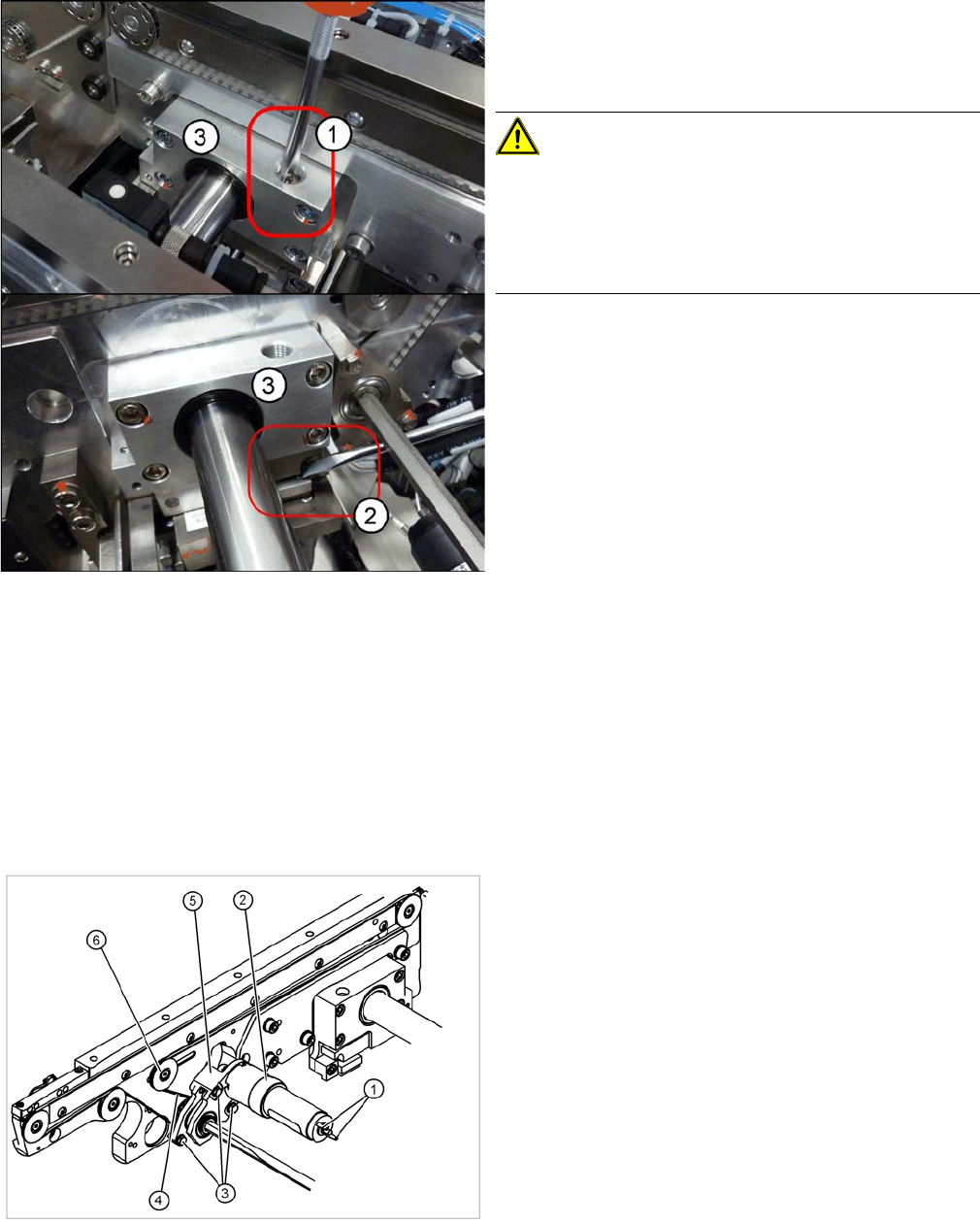
► Loosen the clamps on the conveyor sides.
To do this, loosen the screws (1) holding the
clamps (3) (three per conveyor side) for the relevant
conveyor sides. If one of the clamps is difficult to ac-
cess (e.g. on the intermediate conveyor), you can
also loosen it by lifting the clamp e.g. with a screw-
driver (2).
1. Cable connections
2. Heat-shrinkable sleeve
3. Fastening screws
4. Conveyor toothed belt
5. Motor mount
6. Deflection pulley with slot
The DC geared motors, including the motor mounts of all
5 conveyor areas, are of like construction. Please bear in
mind the following differences during assembly and dis-
assembly:
▪ The motor mount is installed at an angle (tilted), ac-
cording to the requirements of the installation site.
Service Work
3.6.2 Replacing the Complete Drive Unit [00359284-xx] Modular PCB Conveyor System
Service Manual SIPLACE X Series 153
Removal
► Switch off the machine and secure it to prevent unauthorized reactivation.
► Push the Y gantries into the area outside the PCB conveyor.
► Mark the allocation (+/-) of the cable connections (1). This is important for the direction of rotation!
► Disconnect the cable shoes from the motor terminals (1).
► Strip the heat-shrinkable sleeve, (2) used to fasten the connection cable, from the circumference of
the DC geared motor.
► Remove the three screws (3) holding the motor mount in place (5).
► Move the conveyor so that you can easily access the
screws fastening the motor fixtures (3). The convey-
or position with the best access may vary, according
to the conveyor type and area.
► If the drive on the outer fixed edge (single/dual con-
veyor) is replaced, use the machine SW to adjust the
edge until you can access the fixtures for the hexag-
onal shaft. You may need to change the conveyor
mode to fixed side right/left. Make sure that there is
still a gap of 120 mm between the conveyor edges for
the lane concerned.
► Undock the changeover tables to give you more
space to move.
NOTICE
Loosening the deflection pulley
If necessary, loosen the deflection pulley with slot (6). This will make it easier to unthread the
motor mount. The position of this deflection pulley may vary, according to the conveyor area.
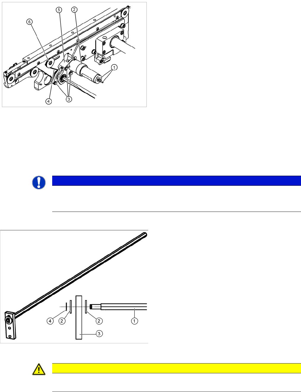
Hexagonal shaft
1. Hexagonal shaft
2. shims
3. Guidance
4. Retaining washer
► Single/dual conveyor: Disconnect the hexagonal
shaft from the conveyor edge (see diagram).
► Quad lane conveyor: First loosen the clamp on the
drive between the conveyor edges.
CAUTION
Do not damage the toothed belt!
The toothed belts must not be stretched or kinked!
Service Work
Modular PCB Conveyor System 3.6.2 Replacing the Complete Drive Unit [00359284-xx]
154 Service Manual SIPLACE X Series
► Single/dual conveyor: Loosen the circlip on the hexagonal shaft and unthread the motor from the
hexagonal shaft.
Quad lane conveyor: Push the drive plus hexagonal shaft to one side and loosen the clamp on the
outer side of the drive. Push the hexagonal shaft off the drive.
Installation
See also
3.6.1 Manual Adjustment of Conveyor Edges [ ➙ 152]
5.4.1 Adjusting the Tension of the Conveyor Toothed Belt [ ➙ 319]
NOTICE
Observe how the belt is run
The way in which the conveyor toothed belt is run around the belt guide depends upon the
transport area concerned. Please observe this belt guidance during assembly.
If you have discovered a break in the motor cable during a continuity check, the motor cable
must be unthreaded as far as the conversion board of the conveyor edge (see circuit diagrams
of the same name) and unplugged at the corresponding point. This might be somewhat com-
plicated depending on the routing of cables inside the machine base.
► You may wish to contact SIPLACE service team regarding this work if you are unsure about
how to proceed.
► Fit the new drive unit in the reverse order.
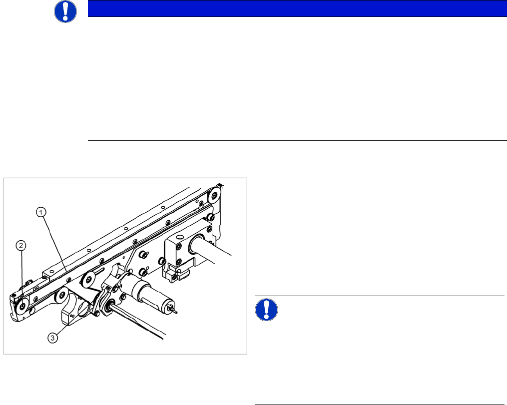
► Please check:
⇨ The entire width of the conveyor toothed belt (1)
must engage at all toothed disks (2) and be run
around the belt guide (3).
⇨ See also "Adjusting the Tension of the Conveyor
Toothed Belt".
► Perform a function test.
NOTICE!
Function test via the station software
After the new drive has been installed, you must make
certain that the direction of rotation and the conveyor
speed (motor voltage) are correct. After connecting the
geared motor, you only need to check the direction of ro-
tation.