00194440-10_SM_X-Series_Customer_en.pdf - 第169页
Service Work 3.6.9 Replacing the Lifting Table Stabilizer (Stabilizer Unit) [00358684-xx] Modular PCB Conveyor System Service Manual SIPLACE X Series 169 Installation and adjustment ► Insert and twist the new stabilizer …
Service Work
Modular PCB Conveyor System 3.6.9 Replacing the Lifting Table Stabilizer (Stabilizer Unit) [00358684-xx]
168 Service Manual SIPLACE X Series
3.6.9
3.6.9 Replacing the Lifting Table Stabilizer (Stabilizer Unit) [00358684-xx]
Replacing the Lifting Table Stabilizer (Stabilizer Unit) [00358684-xx]
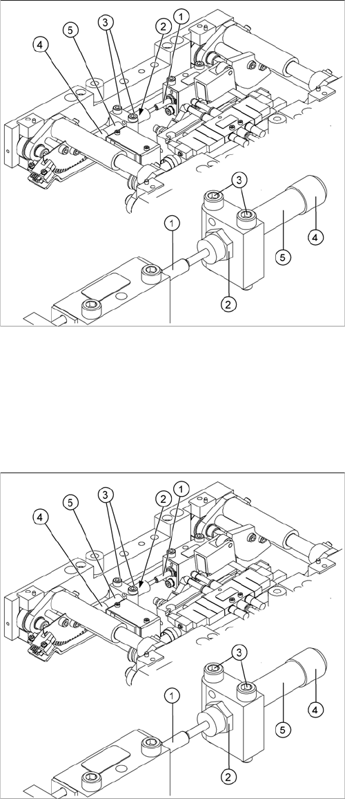
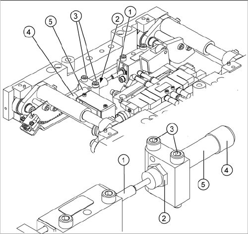
Overview
Tools and equipment required
▪ Torque wrench with plug-in ratchet [00386175-xx]
▪ Plug-in wrench 16 mm [00386177-xx]
Removal
1. Actuator
2. Locknut
3. Fastening screws
4. Handle
5. Stabilizer [00358684-xx]
The stabilizer enables the lifting table to be moved gently
upwards. It prevents the PCBs from being clamped in
with too much impact.
The stabilizer consists of the shock absorber [00367737-
xx] and the damping block [00367782-xx].
► Move the PCB conveyor to the position which gives
you best access to the lifting table.
► Move the Y gantries into the area outside the PCB
conveyor.
► Switch off the machine and secure it to prevent unau-
thorized reactivation.
► Loosen the screws fastening the lifting table plate and
remove the lifting table plate from the lifting table unit.
► Loosen the two screws (3) holding the stabilizer (5).
► Undo the locknut (2) and take the stabilizer by its han-
dle (4), twisting it out of the mounting block.
Service Work
3.6.9 Replacing the Lifting Table Stabilizer (Stabilizer Unit) [00358684-xx] Modular PCB Conveyor System
Service Manual SIPLACE X Series 169
Installation and adjustment
► Insert and twist the new stabilizer (5) until the plunger
just touches the actuator (1), so that the lifting table
can be gently moved upwards.
► Using the torque wrench:
Secure this position with the locknut (2) tightened to
8Nm.
► Check whether the stabilizer has been fixed onto the
mounting block with the locknut and that the stabilizer
plunger has a gap of approx. 0.1 mm to the actuator
(gap in untriggered mode). In this default setting, the
lifting table should move up gently.
► If this is not the case, loosen the locknut and turn the
stabilizer approx. one rotation into the mounting
block.
► Fit the lifting table plate.
► Start SITEST and move the lifting table up.
► The lifting table should move up gently i.e. you should
not hear the PCB clamping device audibly locking
into place and no clamping device error messages
should be issued.
► Check the speed of the lifting table cylinder and cor-
rect where necessary.
Service Work
Modular PCB Conveyor System 3.6.10 Replacing the Lifting Table Solenoid Valve [00358663-xx]
170 Service Manual SIPLACE X Series
3.6.10
3.6.10 Replacing the Lifting Table Solenoid Valve [00358663-xx]
Replacing the Lifting Table Solenoid Valve [00358663-xx]
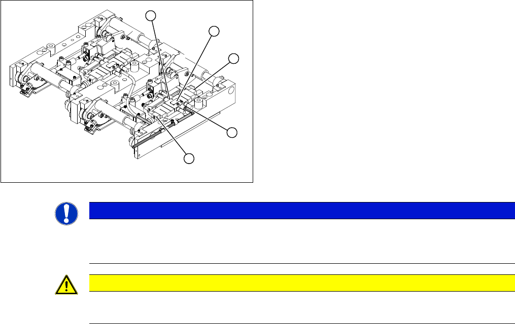
Removal/installation
► Switch off the compressed air supply and release the air at the pneumatic unit filter.
► Loosen the screws fastening the connection plug and then unplug it.
► Remove the compressed air connections.
► Fit the new solenoid valve and reconnect the electrical and compressed air systems.
► Fit the complete lifting table into the machine again.
► Check the speed of the lifting table and correct where necessary.
1. Solenoid valve with two fastening screws
2. Connection plug
3. Compressed air connections
► Move the PCB conveyor to the position which gives
you best access to the lifting table.
► Move the Y gantries into the area outside the PCB
conveyor.
► Switch off the machine and secure it to prevent unau-
thorized reactivation.
► Loosen the screws fastening the lifting table plate and
remove the lifting table plate from the lifting table unit.
3
2
1
3
2
NOTICE
Removing the lifting table
You may wish to completely dismantle the lifting table, to give you better access to the solenoid
valves.
CAUTION
Heavy machine part!
When removing the lifting table, remember it is heavy (17.5 kg).