00194440-10_SM_X-Series_Customer_en.pdf - 第171页
Service Work 3.6.11 Replacing the Lifting Table For k Light Barrier [00363079 -xx] Modular PCB Conveyor System Service Manual SIPLACE X Series 171 3.6.11 3 . 6 . 1 1 R e p la c in g t h e L if t in g T a b le F o r k L i…
Service Work
Modular PCB Conveyor System 3.6.10 Replacing the Lifting Table Solenoid Valve [00358663-xx]
170 Service Manual SIPLACE X Series
3.6.10
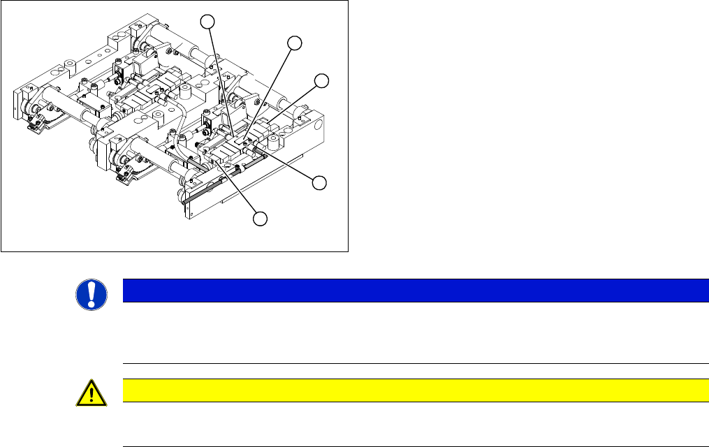
3.6.10 Replacing the Lifting Table Solenoid Valve [00358663-xx]
Replacing the Lifting Table Solenoid Valve [00358663-xx]
Removal/installation
► Switch off the compressed air supply and release the air at the pneumatic unit filter.
► Loosen the screws fastening the connection plug and then unplug it.
► Remove the compressed air connections.
► Fit the new solenoid valve and reconnect the electrical and compressed air systems.
► Fit the complete lifting table into the machine again.
► Check the speed of the lifting table and correct where necessary.
1. Solenoid valve with two fastening screws
2. Connection plug
3. Compressed air connections
► Move the PCB conveyor to the position which gives
you best access to the lifting table.
► Move the Y gantries into the area outside the PCB
conveyor.
► Switch off the machine and secure it to prevent unau-
thorized reactivation.
► Loosen the screws fastening the lifting table plate and
remove the lifting table plate from the lifting table unit.
3
2
1
3
2
NOTICE
Removing the lifting table
You may wish to completely dismantle the lifting table, to give you better access to the solenoid
valves.
CAUTION
Heavy machine part!
When removing the lifting table, remember it is heavy (17.5 kg).
Service Work
3.6.11 Replacing the Lifting Table Fork Light Barrier [00363079-xx] Modular PCB Conveyor System
Service Manual SIPLACE X Series 171
3.6.11
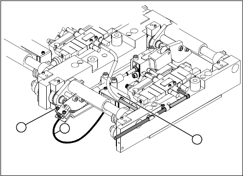
3.6.11 Replacing the Lifting Table Fork Light Barrier [00363079-xx]
Replacing the Lifting Table Fork Light Barrier [00363079-xx]
Parts
▪ Light barrier for track A – dual conveyor [00363079-xx]
▪ Light barrier for track B – dual conveyor [00363080-xx]
▪ Light barrier for track A – single conveyor [00363111-xx]
▪ Light barrier for track B – single conveyor [00363113-xx]
Removal/installation
1. Connection cable for the conversion board of the lift-
ing table
2. Two fork light barriers (distance measuring system
lane A and B)
3. Conversion board of the lifting table (under the cover)
► Move the PCB conveyor to the position which gives
you best access to the lifting table.
► Move the Y gantries into the area outside the PCB
conveyor.
► Switch off the machine and secure it to prevent unau-
thorized reactivation.
► Loosen the screws fastening the lifting table plate and
remove the lifting table plate from the lifting table unit.
► Loosen the two screws (2) fastening the fork light bar-
rier.
► Remove the cover from the conversion board of the
lifting table (3).
► Unplug the lifting table conversion board.
► Fit the new fork light barrier and reconnect to the
electrical system.
1
3
2
Service Work
Modular PCB Conveyor System 3.6.12 Replacing the Complete Lifting Table Cylinder [00358703-xx]
172 Service Manual SIPLACE X Series
3.6.12
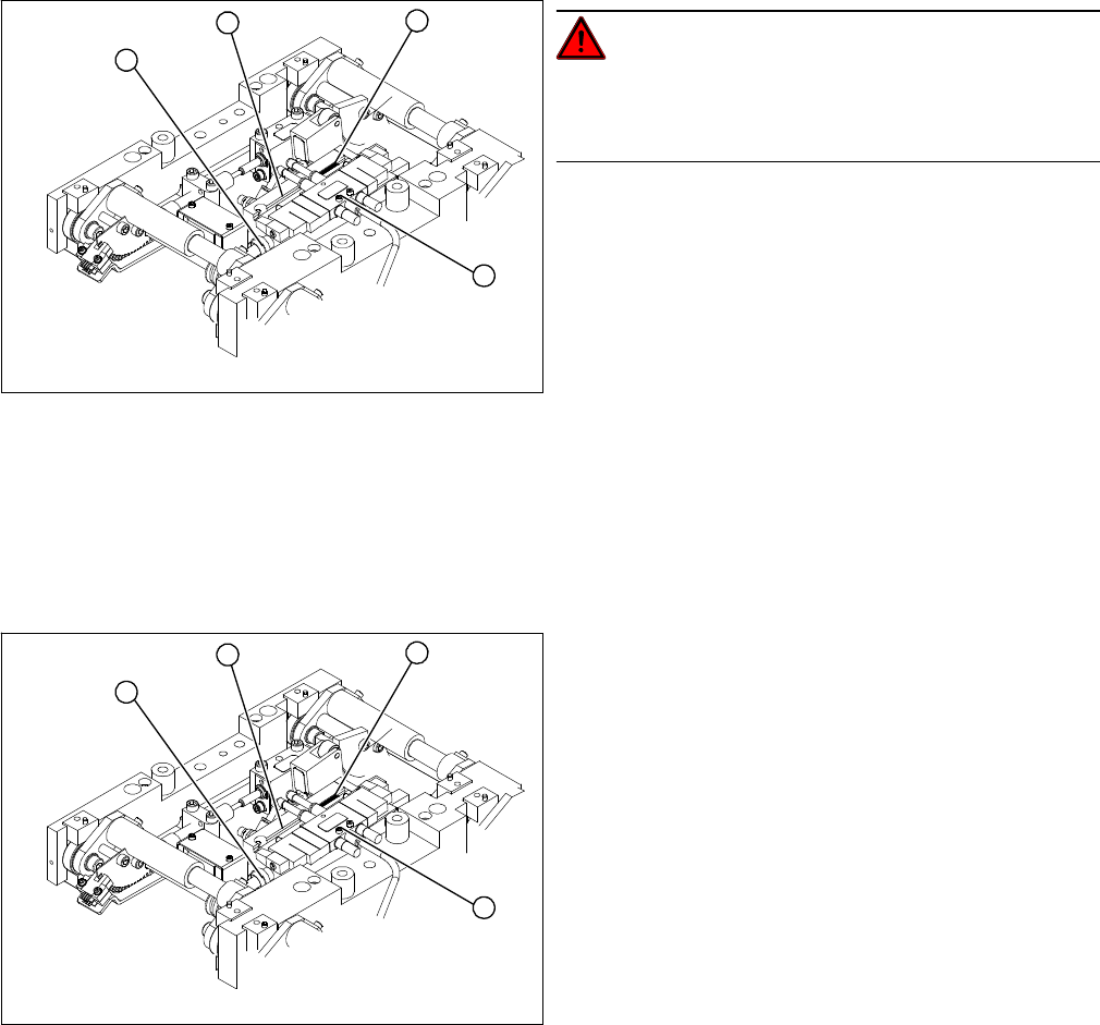
3.6.12 Replacing the Complete Lifting Table Cylinder [00358703-xx]
Replacing the Complete Lifting Table Cylinder [00358703-xx]
Overview
Removal
DANGER!
Press the EMERGENCY STOP!
Before performing adjustment work you must ensure that
the lifting table has been secured against movement.
1. End position proximity switch
2. Lifting table cylinder
3. Piston rod with locknut
4. Solenoid valve
► Move the PCB conveyor to the position which gives
you best access to the lifting table.
► Move the Y gantries into the area outside the PCB
conveyor.
► Switch off the machine and secure it to prevent unau-
thorized reactivation.
► Switch off the compressed air supply.
4
1
3
2
► Loosen the screws fastening the lifting table plate and
remove the lifting table plate from the lifting table unit.
► Loosen the fastening screws for the solenoid valve
(4) and remove it from the lifting table cylinder.
► Loosen the grub screw at the end position proximity
switch (1) and push the end position proximity switch
out of the lifting table cylinder guide rail (2).
► Loosen the locknut on the piston rod (3) and twist the
piston rod out until it releases itself from the actuator.
► Loosen and remove the two screws fastening the lift-
ing table cylinder (2).
4
1
3
2