00194440-10_SM_X-Series_Customer_en.pdf - 第173页
Service Work 3.6.13 Replacing the Limit Switc h for the End Position Width Ad justment System [0 0316831-xx] Modular PCB Conveyor System Service Manual SIPLACE X Series 173 Installation 3.6.13 3 . 6 . 1 3 R e p la c in g…
Service Work
Modular PCB Conveyor System 3.6.12 Replacing the Complete Lifting Table Cylinder [00358703-xx]
172 Service Manual SIPLACE X Series
3.6.12
3.6.12 Replacing the Complete Lifting Table Cylinder [00358703-xx]
Replacing the Complete Lifting Table Cylinder [00358703-xx]
Overview
Removal
DANGER!
Press the EMERGENCY STOP!
Before performing adjustment work you must ensure that
the lifting table has been secured against movement.
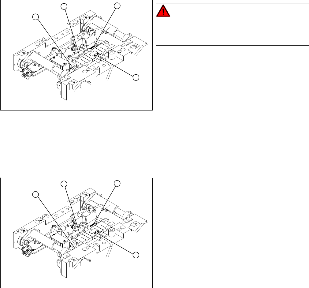
1. End position proximity switch
2. Lifting table cylinder
3. Piston rod with locknut
4. Solenoid valve
► Move the PCB conveyor to the position which gives
you best access to the lifting table.
► Move the Y gantries into the area outside the PCB
conveyor.
► Switch off the machine and secure it to prevent unau-
thorized reactivation.
► Switch off the compressed air supply.
4
1
3
2
► Loosen the screws fastening the lifting table plate and
remove the lifting table plate from the lifting table unit.
► Loosen the fastening screws for the solenoid valve
(4) and remove it from the lifting table cylinder.
► Loosen the grub screw at the end position proximity
switch (1) and push the end position proximity switch
out of the lifting table cylinder guide rail (2).
► Loosen the locknut on the piston rod (3) and twist the
piston rod out until it releases itself from the actuator.
► Loosen and remove the two screws fastening the lift-
ing table cylinder (2).
4
1
3
2
Service Work
3.6.13 Replacing the Limit Switch for the End Position Width Adjustment System [00316831-xx] Modular PCB Conveyor System
Service Manual SIPLACE X Series 173
Installation
3.6.13
3.6.13 Replacing the Limit Switch for the End Position Width Adjustment System [00316831-xx]
Replacing the Limit Switch for the End Position Width Adjustment System [00316831-
xx]
Parts
▪ Limit switch on the assembly tub
▪ Limit switch for width adjustment 1
▪ Limit switch for width adjustment 2
▪ Limit switch for width adjustment - at the conveyor edge
The microswitch [00316831-xx] is used for all limit switches.
Overview
► Insert and fasten the new lifting table cylinder (2) and
install the piston rod (3).
► Move the lifting table by hand to its end position.
► Switch the machine on.
► Push the end position proximity switch (1) into the
guide rail until the LED lights up.
► Fix this position with the grub screw.
► Install the solenoid valve (4) and the lifting table plate.
► Check the speed of the lifting table and correct where
necessary.
4
1
3
2
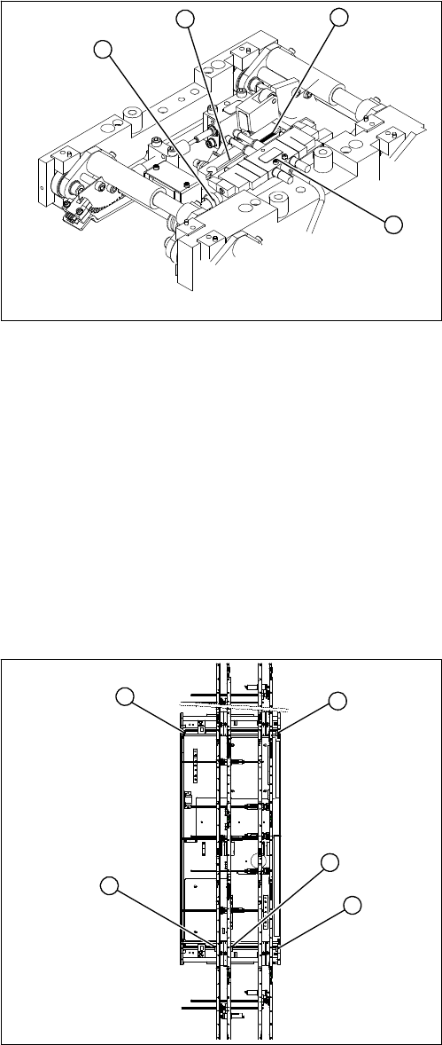
1. Limit switch 1 for width adjustment system of the ad-
justment unit
2. Limit switch for width adjustment system (for side)
3. Limit switch for assembly tub (for side)
4. Limit switch 2 for width adjustment system of the ad-
justment unit
Limit switch on the input conveyor:
There are four limit switches below the conveyor edges
near the input conveyor. The limit switch is designed to
prevent the conveyor edges hitting one another or the
conveyor base.
Limit switch on the output conveyor:
In the vicinity of the output conveyor there are two limit
switches for the adjustment unit. They serve to secure the
transport area and to initialize the adjustment unit during
width adjustment.
2
1
4
3
2
Service Work
Modular PCB Conveyor System 3.6.13 Replacing the Limit Switch for the End Position Width Adjustment System
174 Service Manual SIPLACE X Series
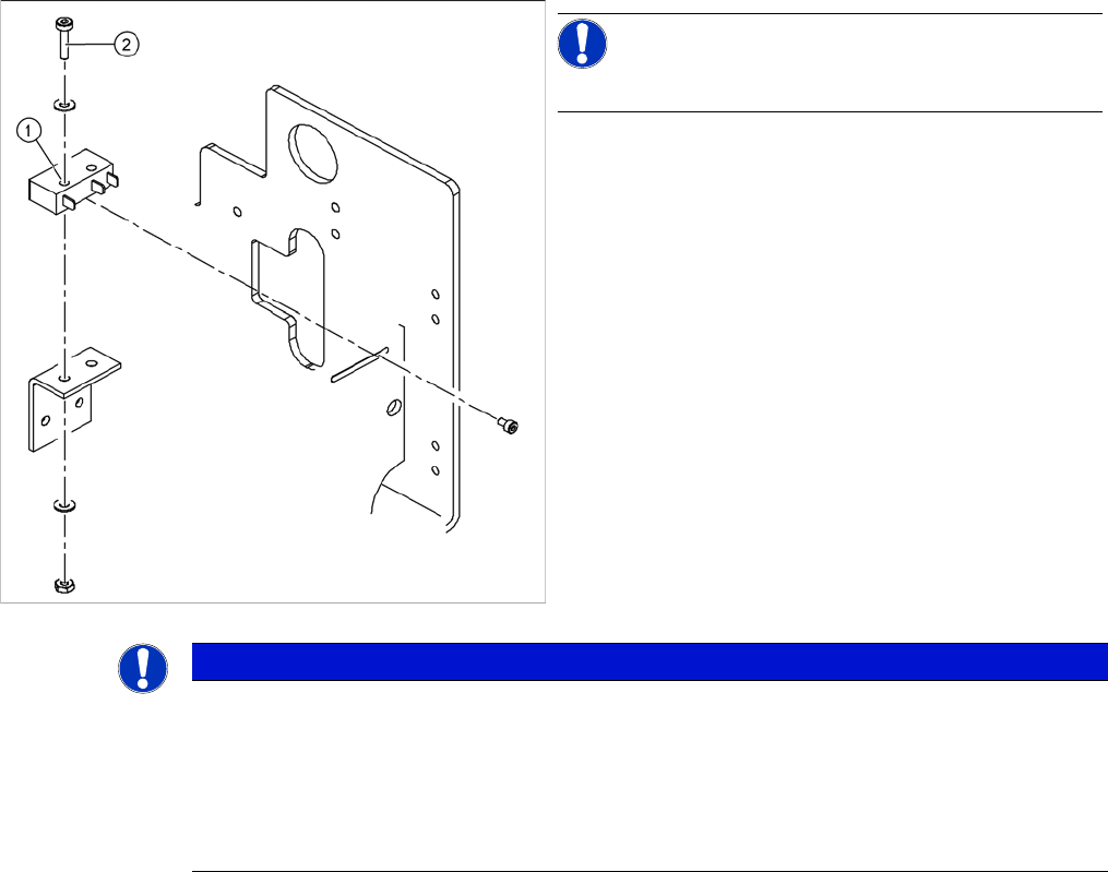
Removal/installation
► Fit the new limit switch and re-solder the connection wires in the correct allocation.
Checking the position of the limit switch:
► Check the minimum and maximum width of the relevant machine type and the parallelism of the con-
veyor edges.
NOTICE!
The limit switches are preassembled and include cables.
However, if the limit switch itself is faulty, the wiring can
be unsoldered/soldered right at the switch in question.
► Unsolder the connection wires on the faulty limit
switch (1).
► Loosen and remove the two screws (2) fastening the
defective limit switch.
NOTICE
Break in limit switch cable
If you have discovered a break in the connection cable during a continuity check, this cable
must be unthreaded as far as the conversion board of the assembly tub and unplugged there.
This might be somewhat complicated depending on the routing of cables inside the machine
base.
► You may wish to contact SIPLACE service team regarding this work.