00194440-10_SM_X-Series_Customer_en.pdf - 第175页
Service Work 3.6.14 Replacing the Light Barri er s for Transmitter and Receive r Modules [00370063- xx] Modular PCB Conveyor System Service Manual SIPLACE X Series 175 3.6.14 3 . 6 . 1 4 R e p la c in g t h e L ig h t B …
Service Work
Modular PCB Conveyor System 3.6.13 Replacing the Limit Switch for the End Position Width Adjustment System
174 Service Manual SIPLACE X Series
Removal/installation
► Fit the new limit switch and re-solder the connection wires in the correct allocation.
Checking the position of the limit switch:
► Check the minimum and maximum width of the relevant machine type and the parallelism of the con-
veyor edges.
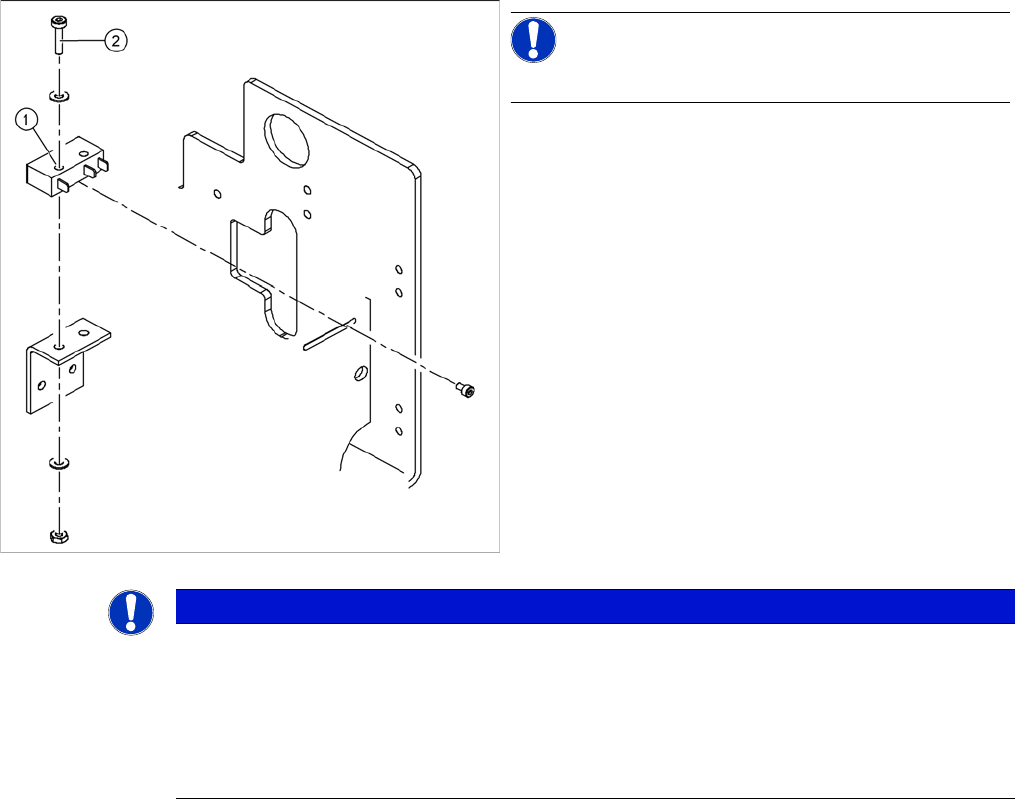
NOTICE!
The limit switches are preassembled and include cables.
However, if the limit switch itself is faulty, the wiring can
be unsoldered/soldered right at the switch in question.
► Unsolder the connection wires on the faulty limit
switch (1).
► Loosen and remove the two screws (2) fastening the
defective limit switch.
NOTICE
Break in limit switch cable
If you have discovered a break in the connection cable during a continuity check, this cable
must be unthreaded as far as the conversion board of the assembly tub and unplugged there.
This might be somewhat complicated depending on the routing of cables inside the machine
base.
► You may wish to contact SIPLACE service team regarding this work.
Service Work
3.6.14 Replacing the Light Barriers for Transmitter and Receiver Modules [00370063-xx] Modular PCB Conveyor System
Service Manual SIPLACE X Series 175
3.6.14
3.6.14 Replacing the Light Barriers for Transmitter and Receiver Modules [00370063-xx]
Replacing the Light Barriers for Transmitter and Receiver Modules [00370063-xx]
Parts
Observe the different item numbers for the individual light barriers, as a result of the varying connection
cable lengths.
The individual item numbers can be found in the applicable catalogue of parts.
Overview
3.6.14.1
3.6.14.1 Replacing the Transmitter or Receiver for Placement Areas 1 and 2
Replacing the Transmitter or Receiver for Placement Areas 1 and 2
Receiver
► Loosen the screw fastening the light barrier.
► Unthread the connection cable as far as the relevant conversion board of the conveyor edge.
► Unplug the conversion board of the conveyor edge.
► Rerun the connection cable accordingly and reconnect the conversion board of the conveyor edge
to the electricity supply.
► Fix the new light barrier in the original position.
Transmitter
► Loosen the two screws fastening the light barrier from the front, through the holes in the supporting
plate.
► Push the supporting plate upwards and unthread the light barrier.
► Unthread the connection cable as far as the relevant conversion board of the conveyor edge.
► Unplug the conversion board of the conveyor edge.
► Rerun the connection cable accordingly and reconnect the conversion board of the conveyor edge
to the electricity supply.
► Fix the new light barrier in the original position.
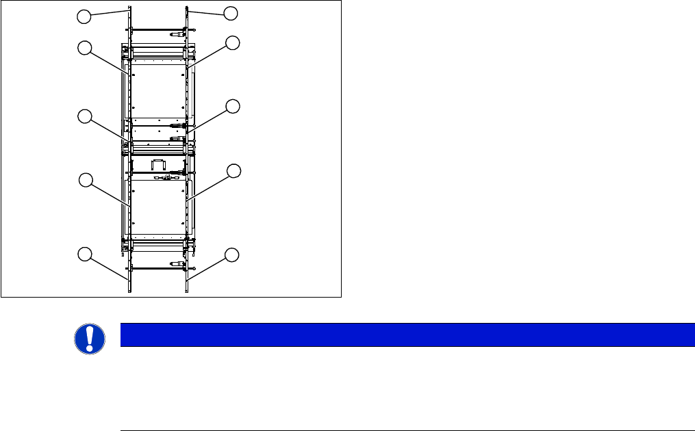
1. Transmitter at input conveyor
2. Receiver at input conveyor
3. Transmitter at placement area 1
4. Receiver at placement area 1
5. Transmitter at intermediate conveyor
6. Receiver at intermediate conveyor
7. Transmitter at placement area 2
8. Receiver at placement area 2
9. Transmitter at output conveyor
10. Receiver at output conveyor
10
9
8
7
1
6
5
4
3
2
NOTICE
Important instructions for replacing the light barrier
► When looking in the direction of transport, the transmitter is always on the left.
► Check whether it would be helpful to feed in the new cable with the aid of the old one, at
least in some areas.
Service Work
Modular PCB Conveyor System 3.6.14 Replacing the Light Barriers for Transmitter and Receiver Modules
176 Service Manual SIPLACE X Series
3.6.14.2
3.6.14.2 Replacing the Transmitter or Receiver for the Input or Output Conveyor
Replacing the Transmitter or Receiver for the Input or Output Conveyor
Receiver
► Loosen the bracket and remove the screws fastening the light barrier.
► Unthread the connection cable as far as the relevant conversion board of the conveyor edge.
► Unplug the conversion board of the conveyor edge.
► Rerun the connection cable accordingly and reconnect the conversion board of the conveyor edge
to the electricity supply.
► Fix the new light barrier in the original position.
Transmitter
► Loosen the screw fastening the light barrier.
► Loosen and remove the six fastening screws from the guide rail.
► Check whether it is possible to unthread the connection cable with its plug.
► Relieve the tension on the conveyor belt, if necessary and remove the deflection pulley at the open-
ing, so that the cable can be unthreaded.
► Unthread the connection cable as far as the relevant conversion board of the conveyor edge.
► Unplug the conversion board of the conveyor edge.
► Rerun the connection cable accordingly and reconnect the conversion board of the conveyor edge
to the electricity supply.
► Fix the new light barrier in the original position.
► Fit the deflection pulley and conveyor toothed belt. Tension the belt.
► After completing the service work, check the PCB clamping function.
NOTICE
Input and output conveyor
The transmitters on the input and output conveyors are freely accessible. The bracket must be
loosened and the screws fastening the light barrier removed.
CAUTION
Align the guide rail parallel to the conveyor edge!
If the guide rail is not aligned parallel, this could result in PCB clamping problems.
NOTICE
Removing the crimp contacts?
Otherwise check whether you can run the cable through the opening by removing the contacts
in the connection plug.