00194440-10_SM_X-Series_Customer_en.pdf - 第178页
Service Work Modular PCB Conveyor System 3.6. 15 Replacing the Laser Light Bar riers for Stopper Positions [00370385-xx] 178 Service Manua l SIPLACE X Series 3.6.15 3 . 6 . 1 5 R e p la c in g t h e L a s e r L ig h t B …
Service Work
3.6.14 Replacing the Light Barriers for Transmitter and Receiver Modules [00370063-xx] Modular PCB Conveyor System
Service Manual SIPLACE X Series 177
3.6.14.3
3.6.14.3 Replacing the Light Barriers for the Intermediate Conveyor
Replacing the Light Barriers for the Intermediate Conveyor
Transmitter
► Loosen the screw fastening the light barrier.
► Pull the side cover out of its guidance.
► Loosen and remove the seven fastening screws from the guide rail.
► Unthread the connection cable as far as the relevant conversion board of the conveyor edge.
► Unplug the conversion board of the conveyor edge.
► Rerun the connection cable accordingly and reconnect the conversion board of the conveyor edge
to the electricity supply.
► Fix the new light barrier in the original position.
► Push the cover plate back in and fit the guide rails parallel to the conveyor side.
While doing this, press the PCB pickup upwards and tighten the seven fastening screws.
► After completing the service work, check the PCB clamping function.
Receiver
► Loosen the bracket and remove the screws fastening the light barrier.
► Unthread the connection cable as far as the relevant conversion board of the conveyor edge.
► Unplug the conversion board of the conveyor edge.
► Rerun the connection cable accordingly and reconnect the conversion board of the conveyor edge
to the electricity supply.
► Fix the new light barrier in the original position.
CAUTION
Align the guide rail parallel to the conveyor edge!
If the guide rail is not aligned parallel, this could result in PCB clamping problems.
NOTICE
Intermediate belt
The transmitter on the intermediate conveyor is freely accessible. The bracket must be loos-
ened and the screws fastening the light barrier removed.
Service Work
Modular PCB Conveyor System 3.6.15 Replacing the Laser Light Barriers for Stopper Positions [00370385-xx]
178 Service Manual SIPLACE X Series
3.6.15
3.6.15 Replacing the Laser Light Barriers for Stopper Positions [00370385-xx]
Replacing the Laser Light Barriers for Stopper Positions [00370385-xx]
Parts
▪ Laser light barrier for transmitter module PA1 assembly [00370385-xx]
▪ Laser light barrier transmitter module PA2 assembly [00370386-xx]
▪ Laser light barrier receiver module PA1 [00365772-xx]
▪ Laser light barrier receiver module PA2 [00365774-xx]
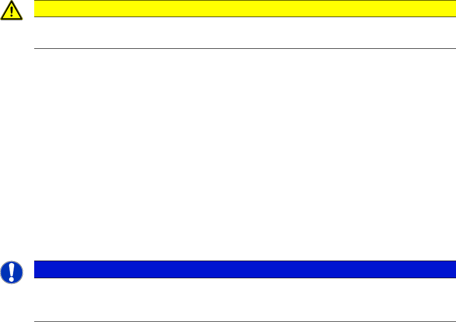
Overview
► Move the PCB conveyor to the position which gives you best access to the laser light barrier.
► Move the Y gantries into the area outside the PCB conveyor.
► Switch off the machine and secure it to prevent unauthorized reactivation.
1. Transmitter module (amplifier) with two screws
2. Transmitter module (round laser diode) with three
screws
DANGER!
The laser light barrier emits class 2 laser beams (from its
transmitter).
You therefore do not require additional protective meas-
ures!
Keep your eyes away from the laser beam!
NOTICE!
Check the PCB reference corner!
After setting the laser light barrier you must check or re-
teach the PCB reference corner!
1
2
Service Work
3.6.15 Replacing the Laser Light Barriers for Stopper Positions [00370385-xx] Modular PCB Conveyor System
Service Manual SIPLACE X Series 179
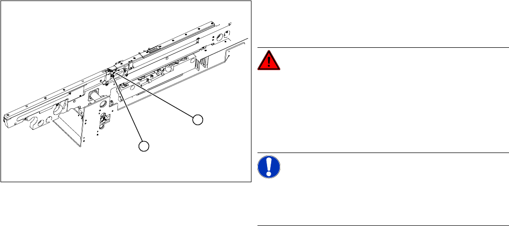
Removal/Installation of complete transmitter module
► Switch the machine on.
► Move the conveyor system to maximum width.
► Turn the three fastening screws to align the transmitter diode centrally to the receiver. The entire
height of the laser beam must hit the receiver.
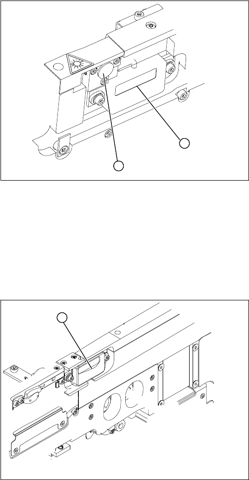
Removal /installation of receiver module
See also
5.4.5 Setting the Laser Light Barrier for the Stopper Position [➙ 331]
► Loosen the two fastening screws on the large trans-
mitter module (1) and the three fastening screws on
the small transmitter module (2). Make sure you do
not lose the O-rings.
► Unthread the connection cable as far as the relevant
conversion board of the conveyor edge.
► Unplug the conversion board of the conveyor edge.
► Rerun the connection cable accordingly and recon-
nect the conversion board on the conveyor edge to
the electrical system.
► Fix the new transmitter module in the original posi-
tion.
► Make sure that the three O-rings are placed on the
three fastening screws.
1
2
► Loosen the two screws fastening the receiver module
(1).
► Unthread the connection cable as far as the relevant
conversion board of the conveyor edge.
► Unplug the conversion board of the conveyor edge.
► Rerun the connection cable accordingly and recon-
nect the conversion board of the conveyor edge to
the electricity supply.
► Fit the new receiver module in the original position.
► Switch the machine on.
► Move the conveyor system to maximum width.
► Turn the two fastening screws to align the receiver
centrally to the transmitter diode. The entire height of
the transmitter diode laser beam must hit the receiv-
er.
1