00194440-10_SM_X-Series_Customer_en.pdf - 第179页
Service Work 3.6.15 Replacing the Laser Light Barriers for Stopper Positions [00370385- xx] Modular PCB Conveyor System Service Manual SIPLACE X Series 179 Removal/Installation of complete transmitter module ► Switch the…
Service Work
Modular PCB Conveyor System 3.6.15 Replacing the Laser Light Barriers for Stopper Positions [00370385-xx]
178 Service Manual SIPLACE X Series
3.6.15
3.6.15 Replacing the Laser Light Barriers for Stopper Positions [00370385-xx]
Replacing the Laser Light Barriers for Stopper Positions [00370385-xx]
Parts
▪ Laser light barrier for transmitter module PA1 assembly [00370385-xx]
▪ Laser light barrier transmitter module PA2 assembly [00370386-xx]
▪ Laser light barrier receiver module PA1 [00365772-xx]
▪ Laser light barrier receiver module PA2 [00365774-xx]
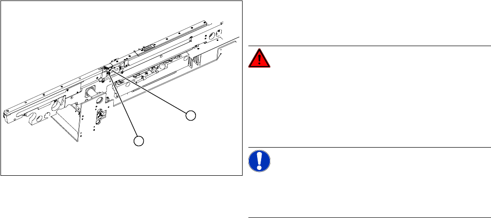
Overview
► Move the PCB conveyor to the position which gives you best access to the laser light barrier.
► Move the Y gantries into the area outside the PCB conveyor.
► Switch off the machine and secure it to prevent unauthorized reactivation.
1. Transmitter module (amplifier) with two screws
2. Transmitter module (round laser diode) with three
screws
DANGER!
The laser light barrier emits class 2 laser beams (from its
transmitter).
You therefore do not require additional protective meas-
ures!
Keep your eyes away from the laser beam!
NOTICE!
Check the PCB reference corner!
After setting the laser light barrier you must check or re-
teach the PCB reference corner!
1
2
Service Work
3.6.15 Replacing the Laser Light Barriers for Stopper Positions [00370385-xx] Modular PCB Conveyor System
Service Manual SIPLACE X Series 179
Removal/Installation of complete transmitter module
► Switch the machine on.
► Move the conveyor system to maximum width.
► Turn the three fastening screws to align the transmitter diode centrally to the receiver. The entire
height of the laser beam must hit the receiver.
Removal /installation of receiver module
See also
5.4.5 Setting the Laser Light Barrier for the Stopper Position [➙ 331]
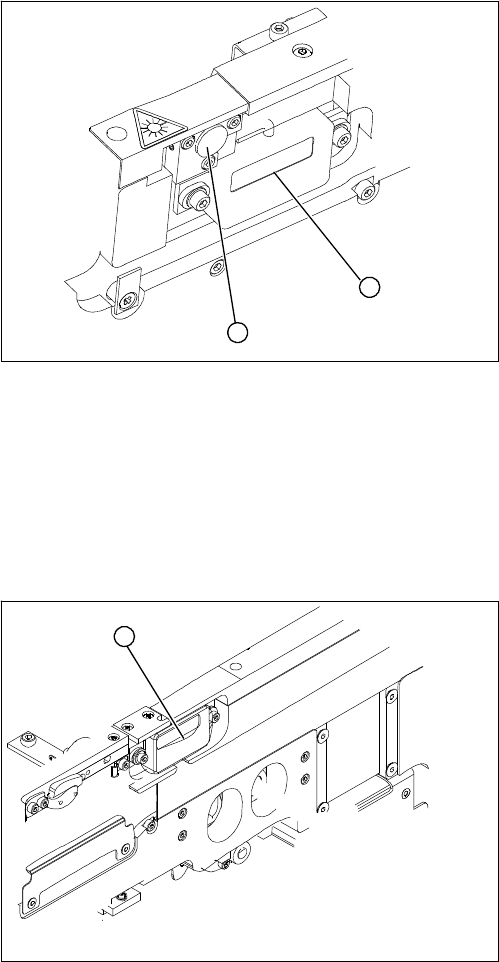
► Loosen the two fastening screws on the large trans-
mitter module (1) and the three fastening screws on
the small transmitter module (2). Make sure you do
not lose the O-rings.
► Unthread the connection cable as far as the relevant
conversion board of the conveyor edge.
► Unplug the conversion board of the conveyor edge.
► Rerun the connection cable accordingly and recon-
nect the conversion board on the conveyor edge to
the electrical system.
► Fix the new transmitter module in the original posi-
tion.
► Make sure that the three O-rings are placed on the
three fastening screws.
1
2
► Loosen the two screws fastening the receiver module
(1).
► Unthread the connection cable as far as the relevant
conversion board of the conveyor edge.
► Unplug the conversion board of the conveyor edge.
► Rerun the connection cable accordingly and recon-
nect the conversion board of the conveyor edge to
the electricity supply.
► Fit the new receiver module in the original position.
► Switch the machine on.
► Move the conveyor system to maximum width.
► Turn the two fastening screws to align the receiver
centrally to the transmitter diode. The entire height of
the transmitter diode laser beam must hit the receiv-
er.
1
Service Work
Modular PCB Conveyor System 3.6.16 Mapping
180 Service Manual SIPLACE X Series
3.6.16
3.6.16 Mapping
Mapping
Tools and Equipment
▪ Mapping test plate HF 508x450 [00373952-xx]
For X series single conveyor 450x508 mm, for dual conveyor rotated by 90°
▪ Mapping test plate 520x300 set [03076124-xx]
This special mapping plate was designed with a width of 300 mm for the quad lane machines. These
machines can only be mapped with this mapping plate, as the conveyor can not be set to a width of
450 mm.
Performing mapping
► Start SITEST.
► Start the overall reference run.
NOTICE
Use the calibration tool [03034148-xx] for the C&P20.
For all other placement heads and the glass mapping plate, use the new calibration tool version
3 [03010565-xx]. This applies for HF, X and D series machines plus for PCB mapping and com-
ponent mapping.
NOTICE
SW70x
The procedure for the SW70x is identical.
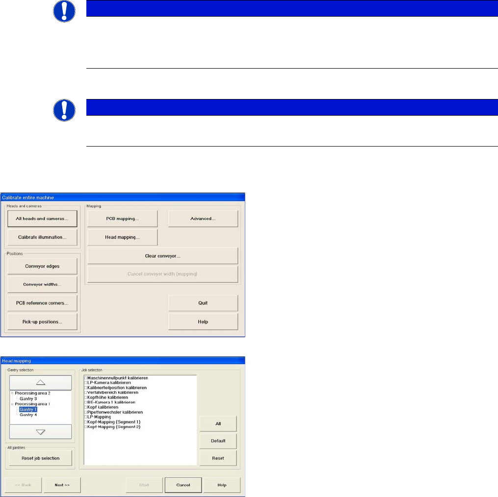
► Go to mode Calibrate machine and select Ad-
vanced... for advanced PCB mapping.
► Select the processing areas and the mapping func-
tions (jobs).