00194440-10_SM_X-Series_Customer_en.pdf - 第180页
Service Work Modular PCB Conveyor System 3.6.16 Mapping 180 Service Manua l SIPLACE X Series 3.6.16 3 . 6 . 1 6 M a p p in g Mapping Tools and Equipment ▪ Mapping test plate HF 508x450 [003 73952-xx] For X series single …
Service Work
3.6.15 Replacing the Laser Light Barriers for Stopper Positions [00370385-xx] Modular PCB Conveyor System
Service Manual SIPLACE X Series 179
Removal/Installation of complete transmitter module
► Switch the machine on.
► Move the conveyor system to maximum width.
► Turn the three fastening screws to align the transmitter diode centrally to the receiver. The entire
height of the laser beam must hit the receiver.
Removal /installation of receiver module
See also
5.4.5 Setting the Laser Light Barrier for the Stopper Position [➙ 331]
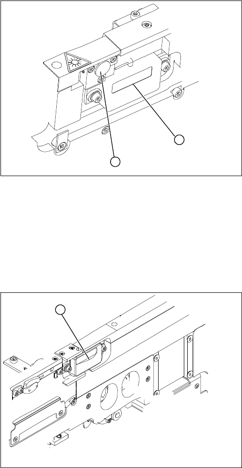
► Loosen the two fastening screws on the large trans-
mitter module (1) and the three fastening screws on
the small transmitter module (2). Make sure you do
not lose the O-rings.
► Unthread the connection cable as far as the relevant
conversion board of the conveyor edge.
► Unplug the conversion board of the conveyor edge.
► Rerun the connection cable accordingly and recon-
nect the conversion board on the conveyor edge to
the electrical system.
► Fix the new transmitter module in the original posi-
tion.
► Make sure that the three O-rings are placed on the
three fastening screws.
1
2
► Loosen the two screws fastening the receiver module
(1).
► Unthread the connection cable as far as the relevant
conversion board of the conveyor edge.
► Unplug the conversion board of the conveyor edge.
► Rerun the connection cable accordingly and recon-
nect the conversion board of the conveyor edge to
the electricity supply.
► Fit the new receiver module in the original position.
► Switch the machine on.
► Move the conveyor system to maximum width.
► Turn the two fastening screws to align the receiver
centrally to the transmitter diode. The entire height of
the transmitter diode laser beam must hit the receiv-
er.
1
Service Work
Modular PCB Conveyor System 3.6.16 Mapping
180 Service Manual SIPLACE X Series
3.6.16
3.6.16 Mapping
Mapping
Tools and Equipment
▪ Mapping test plate HF 508x450 [00373952-xx]
For X series single conveyor 450x508 mm, for dual conveyor rotated by 90°
▪ Mapping test plate 520x300 set [03076124-xx]
This special mapping plate was designed with a width of 300 mm for the quad lane machines. These
machines can only be mapped with this mapping plate, as the conveyor can not be set to a width of
450 mm.
Performing mapping
► Start SITEST.
► Start the overall reference run.
NOTICE
Use the calibration tool [03034148-xx] for the C&P20.
For all other placement heads and the glass mapping plate, use the new calibration tool version
3 [03010565-xx]. This applies for HF, X and D series machines plus for PCB mapping and com-
ponent mapping.
NOTICE
SW70x
The procedure for the SW70x is identical.
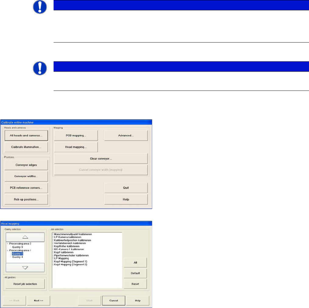
► Go to mode Calibrate machine and select Ad-
vanced... for advanced PCB mapping.
► Select the processing areas and the mapping func-
tions (jobs).
Service Work
3.6.16 Mapping Modular PCB Conveyor System
Service Manual SIPLACE X Series 181
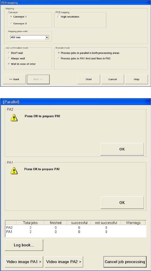
► Select the Conveyor .
► Select the Mapping plate width as 300 mm.
► If you only have one mapping plate available, select
Process jobs in PA1 first and then in PA2.
If you have two mapping plates available, select Pro-
cess jobs in parallel in both processing areas.
► Start the mapping procedure.
You will now be asked to prepare the placement are-
as.