00194440-10_SM_X-Series_Customer_en.pdf - 第183页
Service Work 3.6.17 Replacing the Conveyor C onversion Board Modular PCB Conve yor System Service Manual SIPLACE X Series 183 3.6.17 3 . 6 . 1 7 R e p la c in g t h e C o n v e y o r C o n v e r s io n B o a r d Replacin…
Service Work
Modular PCB Conveyor System 3.6.16 Mapping
182 Service Manual SIPLACE X Series
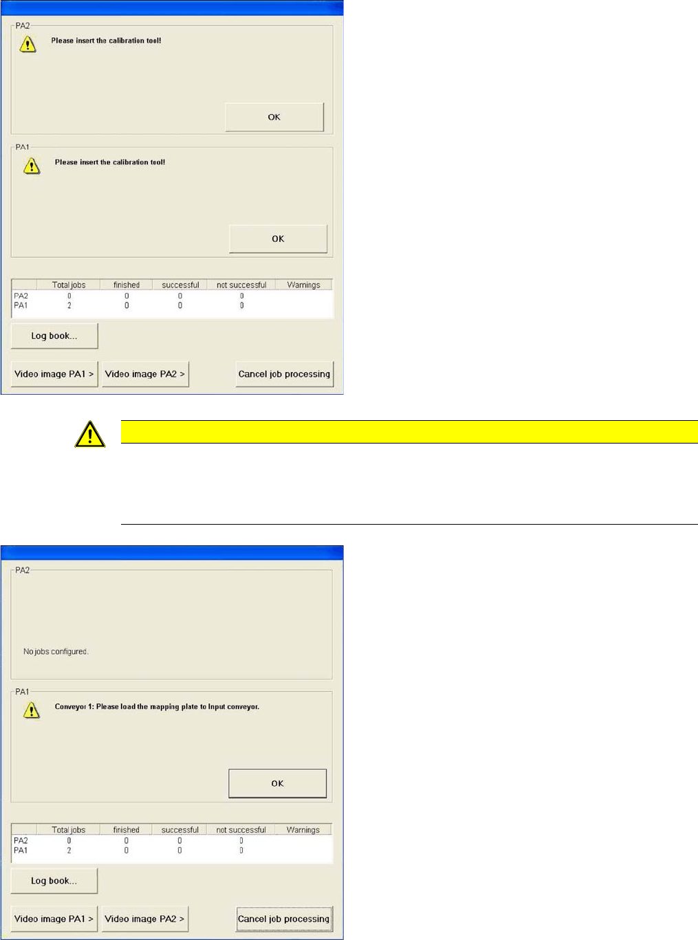
► You will now be asked to insert the calibration tool.
► The nozzle required for component mapping needs to
be set up on all heads.
If this is not the case, you will be asked to change the
nozzle accordingly.
► Read in the correction data.
CAUTION
► When you insert the mapping plate into the conveyor, always make sure that there are no
obstacles (e.g. board supports) on the conveyor lifting table!
► If options are fitted in the conveyor, always check first whether these could cause problems
for the mapping process, otherwise these might damage the mapping plate.
► Once the data is loaded, you will be asked to place
the mapping plate into the input conveyor.
Service Work
3.6.17 Replacing the Conveyor Conversion Board Modular PCB Conveyor System
Service Manual SIPLACE X Series 183
3.6.17
3.6.17 Replacing the Conveyor Conversion Board
Replacing the Conveyor Conversion Board
Parts
The conversion board needed varies according to the conveyor type.
▪ Conveyor Conversion Board (Single and Dual Conveyor) [00359425-xx]
▪ Conveyor Conversion Board (Quad Lane Conveyor) [03066716-xx]
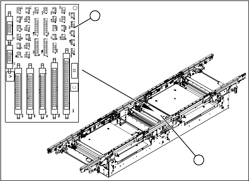
Overview
Removal
► Move the conveyor apart so that you can easily access the working area.
► Switch off the machine.
► Dismantle the cover (2).
► Mark all connections on the conversion board, so that these can be easily allocated again later on.
► Loosen all connections on the conversion board.
► Remove the conversion board from the machine.
Installation
► Fit the new conversion board in the reverse order.
► Then perform a function test.
See also
3.6.22.3 Conveyor Conversion Board (Quad Lane Conveyor) [03066716-xx] [ ➙ 192]
1. Conveyor conversion board
(for single and dual conveyor here)
2. Cover
The conveyor conversion board (1) is situated in place-
ment area 1 underneath the Y axis, in the vicinity of the
intermediate conveyor, under the cover (2).
1
2
Service Work
Modular PCB Conveyor System 3.6.18 Replacing the Conveyor Control Assembly [03071908-xx]
184 Service Manual SIPLACE X Series
3.6.18
3.6.18 Replacing the Conveyor Control Assembly [03071908-xx]
Replacing the Conveyor Control Assembly [03071908-xx]
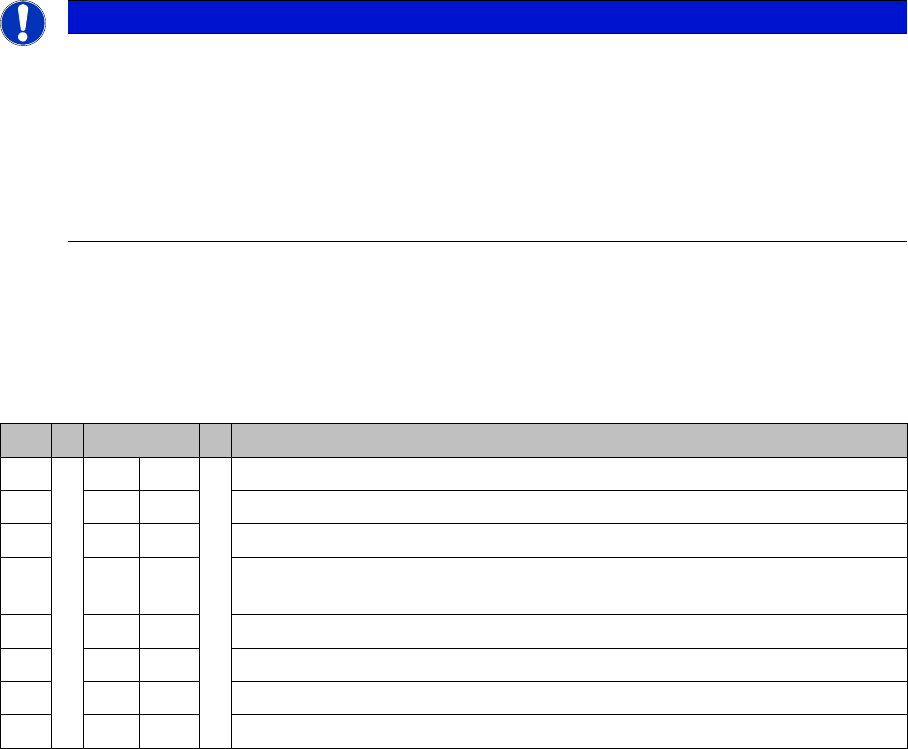
Jumper settings for quad lane
▪ J1, J2 (ao, ap): position 2-3 (SMEMA active)
▪ J3 (ao, ap): position 1-2 (emergency stop loop, not used)
▪ J7 (ao): position 1-2 (CAN bus OFF) (not available for conveyor control TSP301E)
▪ S4 (not available for conveyor control TSP301E):
Parts
The conveyor control (TSP) version required will vary according to the conveyor type concerned (TSP):
▪ Control assembly for single conveyor [00365543-xx]
▪ Control assembly for dual conveyor [00365544-xx]
▪ Control assembly for quad lane conveyor [03071908-xx]
NOTICE
Quad lane
Quad lane conveyors also need the "PCB SMEMA quad lane board" [03067662-xx] and the
SMEMA adapter "SMEMA interface quad lane" [03067541-xx].
These are interfaces which divide the four standard interfaces into eight interfaces.
► When replacing individual boards, make sure that the connection cables are marked and
then reconnected to the boards in their original configuration.
► Pay particular attention to the correct jumper settings.
S S4 Comment
1ON ON
2OFFON: D4 – OFF: SIPLACE X, HF, D3, X4I
3 OFF OFF: Clamping sensor (not used since SW 505)
4ON ON: SIPLACE X2, X3, X4 , X4I (Quad Lane conveyor)
OFF: SIPLACE X2, X3, X4, HF, D4, D3 (standard conveyor)
5OFFNot used
6ON OFF: Standard conveyor – ON: Quad Lane conveyor
7OFFNot used
8OFFNot used