00194440-10_SM_X-Series_Customer_en.pdf - 第190页
Service Work Modular PCB Conveyor System 3.6. 21 Replacing a nd Setting the Sto pper (QC) [03069271-xx] 190 Service Manua l SIPLACE X Series Removal Basic stopper unit fo r quad lane [03 069271 - xx] 1. Stroke lim itatio…
Service Work
3.6.21 Replacing and Setting the Stopper (QC) [03069271-xx] Modular PCB Conveyor System
Service Manual SIPLACE X Series 189
3.6.21
3.6.21 Replacing and Setting the Stopper (QC) [03069271-xx]
Replacing and Setting the Stopper (QC) [03069271-xx]
Overview
► Set the distance between the sensor and the stopper
bolts (2) over the entire length with a feeler gauge (1)
to 0.4 mm and then tighten the screws fastening the
stop rail.
► Reconnect the sensor and fasten the cable with cable
ties.
► Switch on the machine
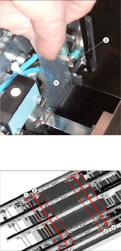
Quad lane conveyor – in the placement area
1. Stopper in input conveyor (four)
2. Stopper in placement area (four)
3. Proximity switches in input conveyor (four)
4. Proximity switches in placement area (four)
The stopper units in the input conveyor need to be dis-
mantled before you can replace spare parts. The stopper
units in the two placement areas may only be dismantled
from the assembly brackets if their positions are then re-
set with a setting gauge, after fitting. The screws need to
be sealed with locking varnish again.
Service Work
Modular PCB Conveyor System 3.6.21 Replacing and Setting the Stopper (QC) [03069271-xx]
190 Service Manual SIPLACE X Series
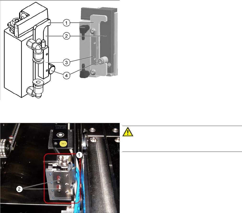
Removal
Basic stopper unit for quad lane [03069271-xx]
1. Stroke limitation rail
2. Stop rail
3. Sensor lower end position stopper [03066803-xx]
4. Stopper bolt
Stopper unit with sonar sensor in the placement area
CAUTION!
Dismantling is only possible if a setting gauge was used
for adjustment.
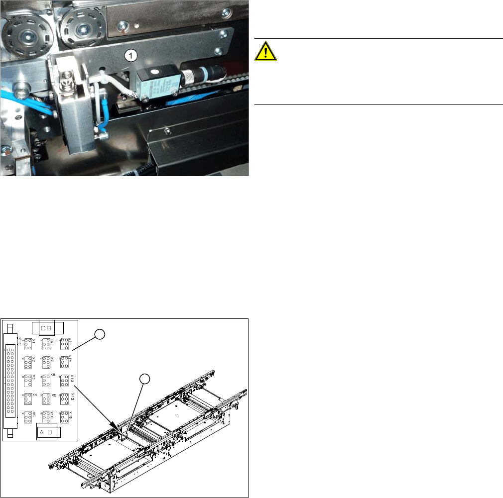
► Move the conveyor to a suitable position in which you
can easily access the stopper (1) . You may need to
undock the relevant component trolley.
► Loosen all electrical and pneumatic connections to
the stopper.
► Loosen the two screws (2) fastened with locking var-
nish and remove the stopper.
Service Work
3.6.22 Overview of the Electrical Components Modular PCB Conveyor System
Service Manual SIPLACE X Series 191
Installation
See also
5.4.7 Readjusting the Holder for the Stopper and Proximity Switch (QC) [ ➙ 338]
3.6.22
3.6.22 Overview of the Electrical Components
Overview of the Electrical Components
3.6.22.1
3.6.22.1 Conveyor Edge Conversion Board [00359424-xx]
Conveyor Edge Conversion Board [00359424-xx]
Overview
► Fit the new stopper.
► Restore all electrical and pneumatic connections.
CAUTION!
If you have loosened or removed the holding fixture (1)
for the stopper and proximity switch during work, this will
need to be readjusted.
1. Conveyor edge conversion board
2. Cover
The conversion boards for the conveyor edges (1) are sit-
uated on the respective conveyor edges, under a cover
(2).
For terminal assignment details, please refer to the cur-
rent version of the circuit diagram folder.
1
2