00194440-10_SM_X-Series_Customer_en.pdf - 第199页
Service Work 3.7.4 Voltage Supply 30V DC-DC Transformer [03020549-xx] X-Serie s COT Insert Service Manual SIPLACE X Series 199 3.7.4 3 . 7 . 4 V o lt a g e S u p p ly 3 0 V D C - D C T r a n s f o r m e r [ 0 3 0 2 0 5 4…
Service Work
X-Series COT Insert 3.7.3 Replacing the 40-Fold Feeder Unlock Device [03011582-xx]
198 Service Manual SIPLACE X Series
3.7.3
3.7.3 Replacing the 40-Fold Feeder Unlock Device [03011582-xx]
Replacing the 40-Fold Feeder Unlock Device [03011582-xx]
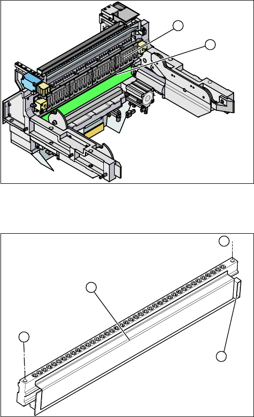
Overview
Removal/installation
1. Feeder unlocking device (under the FCU)
2. Feeder control unit (FCU)
The feeder unlocking device is installed at the locations
in the COT insert.
2
1
1. Two fastening screws
2. Complete feeder unlocking device
3. Connector for flat ribbon cable
► Unplug the flat ribbon cable from the connector (3).
► Loosen the two fastening screws (1) and remove the
complete unit (2).
► Lift up the feeder unlock device by its fixtures and pull
out the flat ribbon cable from the side of the connector
(3).
► Connect the flat ribbon cable.
► Carefully press the feeder unlock device towards the
back and insert the fastening screws (1).
► Make sure that you do not pinch or damage the ca-
bles run at the back (connected to the FCU).
1
1
3
2
Service Work
3.7.4 Voltage Supply 30V DC-DC Transformer [03020549-xx] X-Series COT Insert
Service Manual SIPLACE X Series 199
3.7.4
3.7.4 Voltage Supply 30V DC-DC Transformer [03020549-xx]
Voltage Supply 30V DC-DC Transformer [03020549-xx]
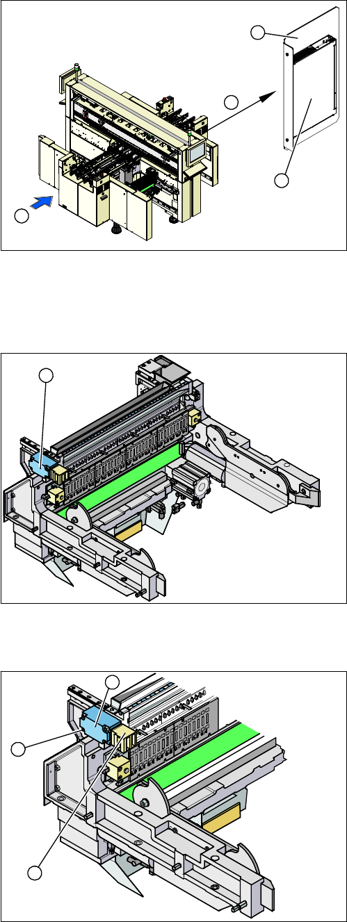
Overview
3.7.5
3.7.5 Replacing the Safety Switch [03019065-xx]
Replacing the Safety Switch [03019065-xx]
Overview
Removal/installation
1. Installation point of voltage supply
2. Power supply
3. Mounting plate
4. Transport direction
4
1
3
2
1. Security switch
The safety switch is installed at the locations in the COT
insert.
1
1. Security switch
2. Four fastening screws
3. Contact jack
► Unplug the connection cable.
► Loosen the four fastening screws (2) and then re-
move the safety switch (1).
► Fit the new safety switch.
► Move the changeover table into the COT insert and
check whether the changeover table can be moved
into the contact jack (3). Correct the position of the
safety switch, where necessary.
► Reconnect to the electricity supply.
3
2
1
Service Work
X-Series COT Insert 3.7.6 Replacing the Empty-Tape Duct Assembly [03021207-xx]
200 Service Manual SIPLACE X Series
3.7.6
3.7.6 Replacing the Empty-Tape Duct Assembly [03021207-xx]
Replacing the Empty-Tape Duct Assembly [03021207-xx]
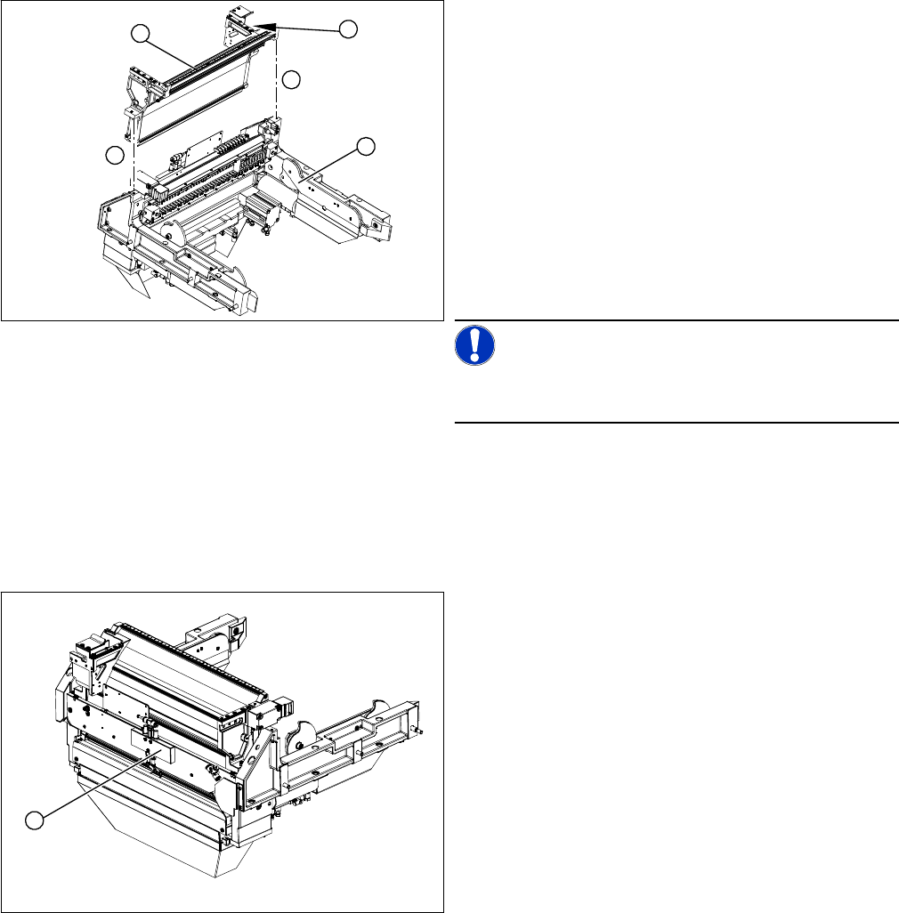
Removal/installation
3.7.7
3.7.7 Replacing the Control Valve [03003489-xx]
Replacing the Control Valve [03003489-xx]
Removal/installation
See also
3.7.1 Replacing the X-Series COT Insert [03015680-xx] [ ➙ 195]
1. COT insert assembly
2. Empty-tape duct assembly
3. Position of the sensors
► Mark the position of the sensors (3) (reed contacts)
and remove these from the reject container.
► Loosen the two screws (4) holding the empty-tape
duct assembly (2).
► Carefully lift the empty-tape duct (2) out of the COT
insert (1).
► Fit the sensors (reed contacts) for the reject contain-
er.
NOTICE!
These sensors are installed in different positions, accord-
ing to the configuration of the machine.
► Fit the empty-tape duct.
4
1
4
3
2
► Remove the complete COT insert from the machine
and place it on a suitable surface.
► Unplug the electricity and compressed air cables
from the control valve (1).
► Loosen the fastening screws and remove the control
valve (1).
► Install the new control valve (1).
► Reconnect to the electrical and compressed air sys-
tems.
► Fit the complete COT insert in the machine.
1