00194440-10_SM_X-Series_Customer_en.pdf - 第204页
Service Work COT Insert HF R2 3.8.2 Replacing the Cable Tree and ODU Connecto r [03006855-xx] 204 Service Manua l SIPLACE X Series 3.8.2 3 . 8 . 2 R e p la c in g t h e C a b le T r e e a n d O D U C o n n e c t o r [ 0 …
Service Work
3.8.1 Replacing the COT Insert Assembly [03000811-xx] COT Insert HF R2
Service Manual SIPLACE X Series 203
Location COT insert
Designator / Cable
Basic Machine
Plug / Cable
1 Power supply 03001288 X111 03002491
Signaling 03006857 X112 03002541
Security 03006858 X113 03002542
Nozzle changer 03001295 X114 03002543
CAN-IN 03006856 X115 03010051
CAN-Out 03006856 X116 03010050
2 Power supply 03001288 X121 03002492
Signaling 03006857 X122 03002530
Security 03006858 X123 03002531
Nozzle changer 03001295 X124 03002532
CAN-IN 03006856 X125 03010053
CAN-Out 03006856 X126 03010054
3 Power supply 03001288 X131 03002493
Signaling 03006857 X132 03002534
Security 03006858 X133 03002535
Nozzle changer 03001295 X134 03002536
CAN-IN 03006856 X135 03010056
CAN-Out 03006856 X136 03010057
4 Power supply 03001288 X141 03002494
Signaling 03006857 X142 03002546
Security 03006858 X143 03002547
Nozzle changer 03001295 X144 03002548
CAN-IN 03006856 X145 03010051
CAN-Out 03006856 X146 03010052
CAUTION!
Heavy machine part!
The COT insert is heavy. You will need to enlist the help
of a second strong person to help you lift it out.
► Loosen the screws fastening the COT insert (1).
► Loosen the fitting screw (2) on the inside of the ma-
chine.
► Lift the complete COT insert out of the machine and
place it on a suitable surface (four wooden blocks
etc.).
► Make sure that you do not damage any valves, con-
nection cables, hoses etc.
► Fit the new COT insert and reconnect all cables.
► Run the cables and hoses through the opening in the
machine base.
1
1
1
1
2
1
Service Work
COT Insert HF R2 3.8.2 Replacing the Cable Tree and ODU Connector [03006855-xx]
204 Service Manual SIPLACE X Series
3.8.2
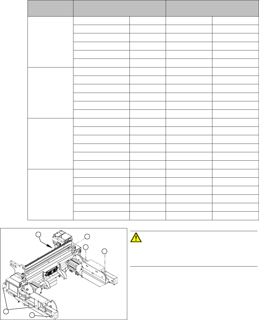
3.8.2 Replacing the Cable Tree and ODU Connector [03006855-xx]
Replacing the Cable Tree and ODU Connector [03006855-xx]
Overview
1. ODU connector with cable tree
2. Cover
3. Centering bar
► Remove the complete COT insert from the machine
and place it on a suitable surface.
► Remove the slider (5) on the ODU connector (1).
► Loosen the screws fastening the covers (2) and re-
move the covers (2).
► Loosen the screws fastening (4) the centering bar (3).
► Remove the centering bar (3).
► Loosen the fastening screws on the ODU connector
(1).
► Unthread and then disconnect the electrical and com-
pressed air connection cables (2).
► Remove any cable ties and the spiral hose..
► Note how the cables are run.
CAUTION!
Check how the cables are run!
Make sure that the cables attached to the ODU connector
are not under strain!
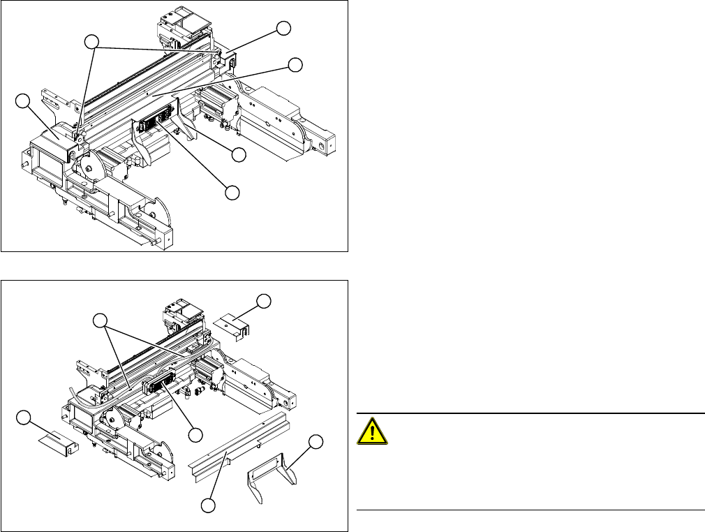
► Install the new ODU connector (1) and reconnect to
the electrical and compressed air systems.
► Run the cables and hoses, using the spiral hose and
cable ties.
► Fit the centering bar (3), the covers (4) and the slider
(5).
1
2
3
4
5
2
4
1
5
4
3
2
Service Work
3.8.3 Replacing the Undocked Component Trolley Short-Stroke Cylinder [03002876-xx] COT Insert HF R2
Service Manual SIPLACE X Series 205
3.8.3
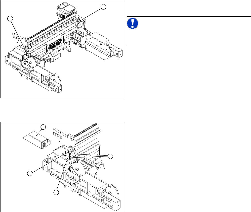
3.8.3 Replacing the Undocked Component Trolley Short-Stroke Cylinder [03002876-xx]
Replacing the Undocked Component Trolley Short-Stroke Cylinder [03002876-xx]
Overview
Removal/installation
1. Undocked short-stroke cylinder for the component
trolley
NOTICE!
The COT insert can remain fully assembled and does not
need to be removed from the machine.
1
1
► Loosen the screw fastening the cover (2).
► Disconnect the compressed air connection (3) from
the short-stroke cylinder (1).
► Loosen the two screws (4) fastening the short-stroke
cylinder.
► Install the new short-stroke cylinder (1) and recon-
nect to the compressed air system (3).
► Run the cables and hoses again under the cover (2).
Make sure you do not damage the cables and hoses.
1
4
3
2