00194440-10_SM_X-Series_Customer_en.pdf - 第211页
Service Work 3.9.1 Replacing the Cutter [03052900-xx] on th e R2 COT Insert Cutter Service Manual SIPLACE X Series 211 3.9.1 3 . 9 . 1 R e p la c in g t h e C u t t e r [ 0 3 0 5 2 9 0 0 - x x ] o n t h e R 2 C O T I n s…
Service Work
Cutter 3.8.7 Replacing the Baffles [03002191-xx]
210 Service Manual SIPLACE X Series
3.9
3.9 Cutter
Cutter
The removal procedure for the cutter may differ, depending on the COT insert used.
Observe the specifications for the relevant COT insert.
Cutter on HF R2 COT insert
Cutter on X-Series COT insert
See also
3.9.1 Replacing the Cutter [03052900-xx] on the R2 COT Insert [ ➙ 211]
3.9.2 Replacing the Cutter [03052900-xx] on the X-Series COT Insert [ ➙ 213]
1. COT Insert HF R2
2. Cutter
1
2
1. X-Series COT Insert
2. Cutter
1
2
Service Work
3.9.1 Replacing the Cutter [03052900-xx] on the R2 COT Insert Cutter
Service Manual SIPLACE X Series 211
3.9.1
3.9.1 Replacing the Cutter [03052900-xx] on the R2 COT Insert
Replacing the Cutter [03052900-xx] on the R2 COT Insert
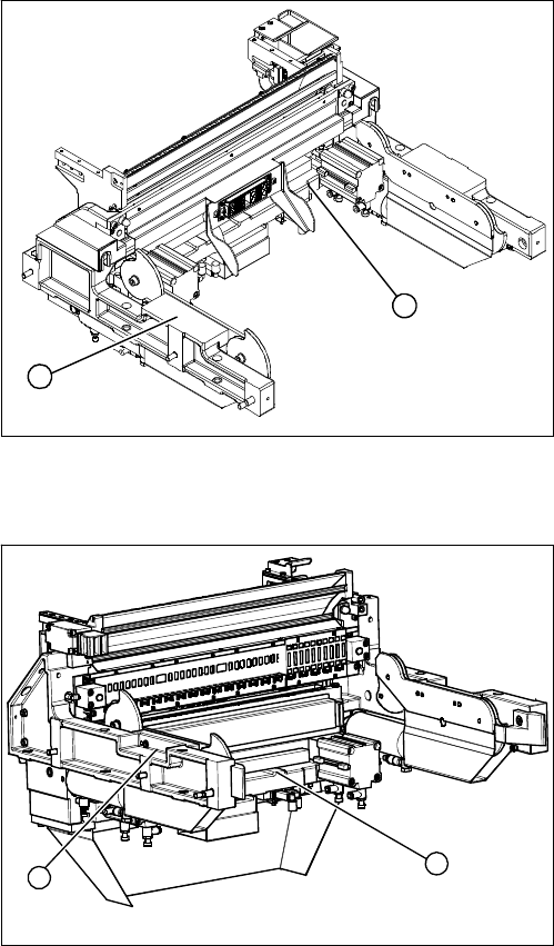
Removing the ODU connector and centering bar
Removing the empty-tape duct assembly
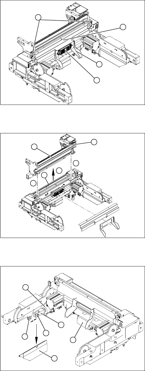
Dismantling the round cylinder
► Remove the slider (2) on the ODU connector (1).
Make sure you do not lose the spacer bolts.
► Loosen the screws fastening (4) the centering bar (3).
► Remove the centering bar (3).
1
2
3
4
► Loosen the screws (1) holding the empty-tape duct
assembly (2).
► Carefully lift the empty-tape duct out of the COT in-
sert (3).
► Mark the position of the sensors (4) (reed contacts)
and remove these from the reject container.
► Remove the rear baffles (5).
1
1
3
5
4
2
► Remove the left (viewed from the front) cylinder cov-
ers (1) and perform the following steps to the left
round cylinder (5):
► Undo the circlip (2) on the fork head (3) with a suitable
pair of circlip pliers.
► Carefully knock the shaft out of the guidance. Pay at-
tention to the two shim rings (4).
The round cylinder (5) is now hanging on the back
shaft.
► Loosen the compressed air connections for the short-
stroke cylinder at the coupling.
► Remove the cover on the control unit (6) and unplug
the electrical connections from the control unit (6)
(CAN bus and supply voltage).
5
6
1
4
3
2
Service Work
Cutter 3.9.1 Replacing the Cutter [03052900-xx] on the R2 COT Insert
212 Service Manual SIPLACE X Series
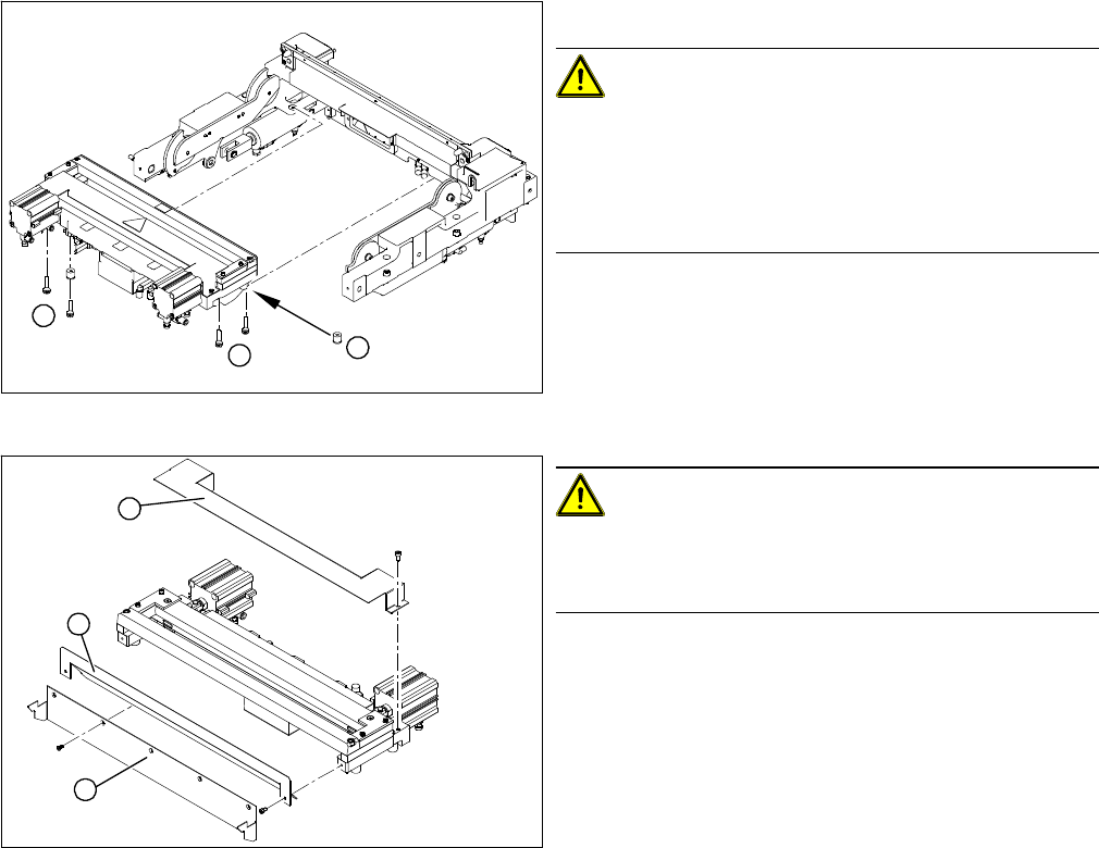
Removing the cutter
Installing the cutter
► Carefully lift the cutter onto the spacer sleeves. Use the spacer disks if provided.
► Tighten all four fastening screws.
► Reconnect to the electrical and compressed air systems.
► Fit the round cylinder and cylinder cover.
► Loosen the four screws (1) fastening the cutter.
CAUTION!
Make sure that assembly is performed correctly!
Please note that spacer sleeves may be used under the
rear fastening screws (2), if necessary. There may also
be other shims in-between, which will then need to be fit-
ted back in the correct position after service work.
The spacer sleeves and the fastening screw are secured
with free rotation in groove. This prevents the screw and
spacer sleeve from falling out and facilitates easier rein-
stallation of the cutter.
► Carefully lift the cutter out of the machine.
CAUTION!
There is a risk of injuring yourself on the cutting edge of
the blades. For this reason, the deflector plate (2), cover
(1) and protective sheet (3) must be left mounted in place.
1
1
2
1
3
2