00194440-10_SM_X-Series_Customer_en.pdf - 第215页
Service Work 3.9.3 Replacing the Articulated Joint on the Short-Stroke C ylin der [03000518-xx] Cutter Service Manual SIPLACE X Series 215 3.9.3 3 . 9 . 3 R e p la c in g t h e A r t ic u la t e d J o in t o n t h e S h …
Service Work
Cutter 3.9.2 Replacing the Cutter [03052900-xx] on the X-Series COT Insert
214 Service Manual SIPLACE X Series
Installing the cutter
► Remove the two fixtures (1) on the left and right and
attach these with the spacer sleeves (2) to the new
cutter.
⇨ There may also be other shims in-between, which
will then need to be fitted back in the correct posi-
tion after service work.
► Carefully lift the cutter onto the spacer sleeves. Use
the spacer disks if provided.
► Tighten all four fastening screws.
CAUTION!
There is a risk of injuring yourself on the cutting edge of
the blades.
For this reason, the deflector plate (2), cover (1) and pro-
tective sheet (3) must be left mounted in place.
► Move the cutter (1) into its installation position, using
the support/chair for assistance.
► Carefully lift the cutter (1) into the planned position.
► Tighten all four fastening screws (2).
► Reconnect to the electrical and compressed air sys-
tems.
► Fit the waste tape container (3).
2
1
1
3
2
2
1
3
2
Service Work
3.9.3 Replacing the Articulated Joint on the Short-Stroke Cylinder [03000518-xx] Cutter
Service Manual SIPLACE X Series 215
3.9.3
3.9.3 Replacing the Articulated Joint on the Short-Stroke Cylinder [03000518-xx]
Replacing the Articulated Joint on the Short-Stroke Cylinder [03000518-xx]
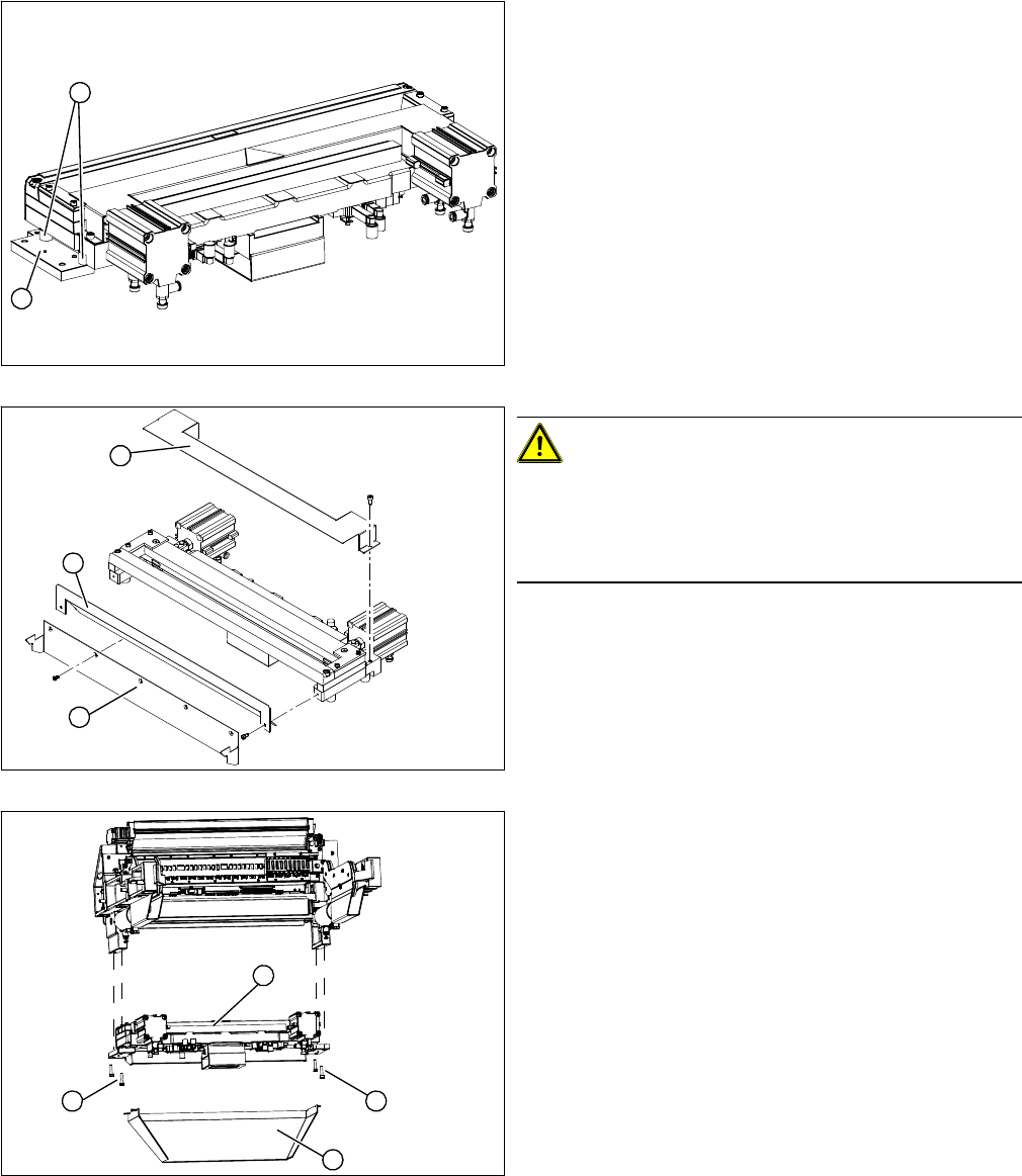
Removing the articulated joint
► Dismantle the COT insert and the cutter.
► Remove the protective plate (2) and the baffle plate
(3).
► Remove the cover plate (1).
► Remove the caps (4) on the fastening screws.
1. Articulated joint on the short-stroke cylinder
2. Fastening screw on moveable blade.
► Loosen the screw (2) holding the moveable blade.
CAUTION!
Risk of injury!
There is a risk of injuring yourself on the cutting edge of
the blades.
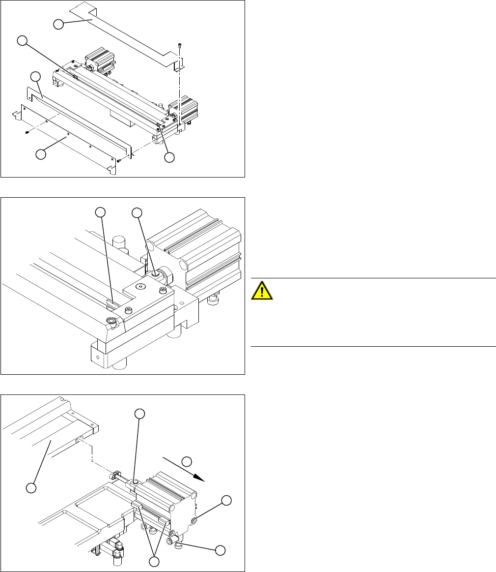
► Use a permanent marker to mark the exact installa-
tion position of the proximity switch (1) on the short-
stroke cylinder. Mark the hoses.
► Loosen the screws fastening the two inductive prox-
imity switches (1) to the short-stroke cylinder.
► Remove the compressed air connections (2) on the
short-stroke cylinder.
► Remove the two screws (3) holding the short-stroke
cylinder.
► Pull the short-stroke cylinder (4) and the articulated
joint screwed into it (5) out of the cutter set (6).
4
1
4
3
2
1
2
1
6
5
4
3
2
Service Work
Cutter 3.9.3 Replacing the Articulated Joint on the Short-Stroke Cylinder [03000518-xx]
216 Service Manual SIPLACE X Series
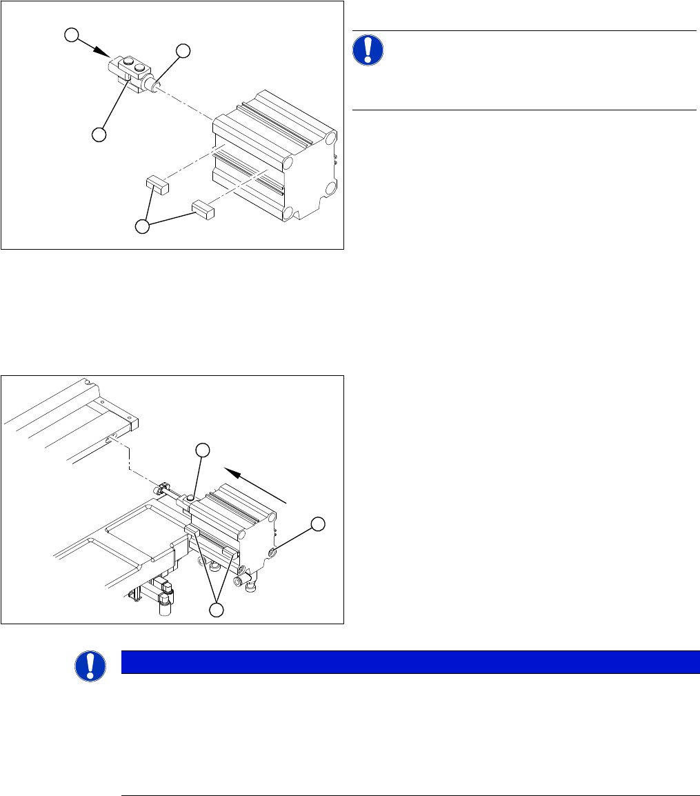
Installing the articulated joint
► Unscrew the articulated joint (1) from the cylinder.
NOTICE!
The threaded pin is secured with Loctite no 241. You will
need somewhat more strength than usual to loosen it.
► Apply a small amount of Loctite no. 241 to the thread
(2) of the new joint.
► Screw the articulated joint (1) into the short-stroke
cylinder.
► Turn the articulated joint in its installation position (3).
Once the cylinder is installed, the slot in the moveable
blade prevents the articulated joint from turning.
► Copy the exact installation position of the proximity
switch (4) onto the new short-stroke cylinder (e.g.
with a feeler gauge, fine-tipped marker pen).
1
4
3
2
► Install the proximity switch (1) precisely in the position
you marked with the permanent marker.
► Place the prepared cylinder into the cutter, in the cor-
rect rotary position of the articulated joint (2).
► Fasten the cylinder in this position, with the two
screws provided (3).
► Connect the compressed air hoses to the cylinder in
the correct allocation.
► Check the gap between the leading edge of the tape
deflector and the "empty-tape baffle, inside".
► Check the switching points of the proximity switches.
1
3
2
NOTICE
If the tapes are not cut correctly.
If the tapes are not cut correctly, even though the switching points have been set properly and
the short-stroke cylinder has been exchanged - complete with the one-way restrictor - the cause
of the problem may be:
► Incorrect compressed air level
► Leaking compressed air connection or Y-socket union