00194440-10_SM_X-Series_Customer_en.pdf - 第220页
Service Work Cutter 3.9.6 Rep lacing the Proximity Switch (FSE) [00332894-xx] 220 Service Manua l SIPLACE X Series Removal/installation 3.9.6 3 . 9 . 6 R e p la c in g t h e P r o x im it y S w it c h ( F S E ) [ 0 0 3 3…
Service Work
3.9.5 Replacing the Solenoid Valves [03000630-xx] Cutter
Service Manual SIPLACE X Series 219
Comparison of board press fit connections
3.9.5
3.9.5 Replacing the Solenoid Valves [03000630-xx]
Replacing the Solenoid Valves [03000630-xx]
Overview
Tape control unit [03006411-xx] CAN nodes NC tape cutter X/HF [03052927-xx]
Not connected X1 Energy supply with automatic CAN ID
Voltage supply for cutter +24 V and +5 V X2 X2 Energy supply, cutter +24 V/+5 V
Not connected X3 Sensors for reject container (nozzles, com-
ponents)
CAN bus connection X4 X4 CAN bus connection
Voltage supply to valve (left) X5 X5 Voltage supply to valve (left)
Voltage supply to valve (right) X6 X6 Voltage supply to valve (right)
Proximity switch for stroke cylinder in (left) X7 X7 Proximity switch for stroke cylinder move in
(left)
Proximity switch for stroke cylinder out
(left)
X8 X8 Proximity switch for stroke cylinder move out
(left)
Proximity switch for stroke cylinder in
(right)
X9 X9 Proximity switch for stroke cylinder move in
(right)
Proximity switch for stroke cylinder out
(right)
X10 X10 Proximity switch for stroke cylinder move out
(right)
X11 Test connector for cutter
X12 Air blast valve (additional air blast unit on the
nozzle station)
X13 Nozzle changer, row 1
X14 Nozzle changer, row 2
Jumper for location code of cutter: X12 S3 S3 DIP switch group S3
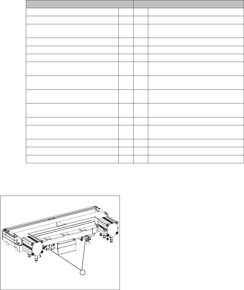
1. Position of the solenoid valves
1
Service Work
Cutter 3.9.6 Replacing the Proximity Switch (FSE) [00332894-xx]
220 Service Manual SIPLACE X Series
Removal/installation
3.9.6
3.9.6 Replacing the Proximity Switch (FSE) [00332894-xx]
Replacing the Proximity Switch (FSE) [00332894-xx]
Overview
Removal/installation
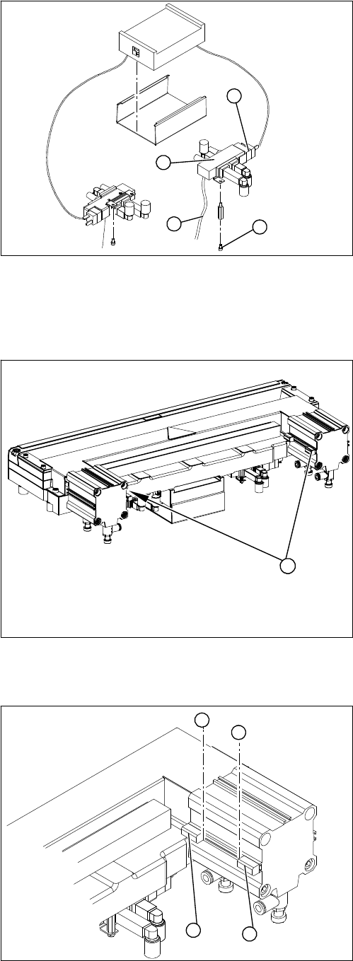
1. Solenoid valve assembly
► Loosen the compressed air connections (3) on the
solenoid valve.
► Unplug the press-fit connection (2) on the solenoid
valve connection cable.
► Loosen the screws (4) holding the solenoid valve in
place and remove the solenoid valve.
► Mount the new solenoid valve and make the press-fit
connection to the valve.
Attach cables ties, if necessary (strain relief).
1
4
3
2
1. Two proximity switches each on the short-stroke cyl-
inder
1
► Use a permanent marker to mark the exact installa-
tion position (3) of the proximity switch (1) or (2) on
the short-stroke cylinder.
► Loosen the screw fastening the proximity switch to
the short-stroke cylinder.
► Unthread the connection cable to the control unit.
► Install the proximity switch precisely in the position (3)
you marked with the permanent marker on the short-
stroke cylinder.
► Secure the fastening screws with locking varnish..
► Reconnect to the electricity supply.
► Check the switching points of the proximity switches.
1
2
3
3

Service Work
3.9.7 Replacing the Cutter Blades Cutter
Service Manual SIPLACE X Series 221
3.9.7
3.9.7 Replacing the Cutter Blades
Replacing the Cutter Blades
Parts, equipment and tools
Select the right set of blades.
We recommend the following additional spare parts:
▪ 2x blade cover (cutter HF) [03000553-xx] (cover for screws of movable blades)
▪ 2x ISO4762-M5x35-12.9, geomet 321+VL [03057290-xx] (screws for movable blades)
▪ 2x articulated joint (cutter HF) [03000518-xx]
▪ 2x DIN71412-BM6 [03036943-xx] (lubrication nipple)
Consumables required:
▪ Lubricant grease Klüber BEM 34-132 tin 1 kg [00374565-xx] (identical to the lubricant grease used
on the guide carriage of the gantry)
▪ Interflon Fin Grease [03020782-xx]
▪ LOCTITE 243 screw locking varnish [00334892-xx]
Tools required
▪ Extra protection gloves, leather [00091001-xx]
▪ Torx screwdriver ESD 1.0-5.0 Nm [03078400-xx]
▪ Torque wrench 2.5 - 25 Nm [00376625-xx]
▪ Bit holder for TorqueVario screwdriver [03078706-xx]
▪ Socket-head bit size 3-6
▪ Fork wrench, size 10
▪ Feeler gauge
▪ Brush
▪ Cloth
▪ Two large parallel clamps and a sturdy table with even surface, to clamp down the dismantled cutter
CAUTION
Risk of injury!
There is a high risk of injury from the blades and the tape deflector.
► Wear appropriately thick protective gloves!
► Never reach into the cutter from below or into the empty-tape duct from above.
► Make sure that no-one can injure themselves on the cutter after it has been dismantled and
placed next to the machine!
Machine Tape cutter, pneumatic Function status Set of blades
X series, SX4, DX4, X
series S
03066690-xx
(without CAN nodes)
-01 03009259-xx
HF, X series 03000487-xx -01 to -03 03000501-xx
-04 to -05 03009259-xx
X Series 03019941-xx
(with control unit)
-01 03009259-xx
03052900-xx
(with CAN nodes)
-01 to -02 03009259-xx