00194440-10_SM_X-Series_Customer_en.pdf - 第226页
Service Work X-Series Component Trolley 3.10.1 R eplacing the Fixed/Guide Ca st ors [00341918-xx] 226 Service Manua l SIPLACE X Series ► Further installation is performe d by following the above instru ctions in the reve…
Service Work
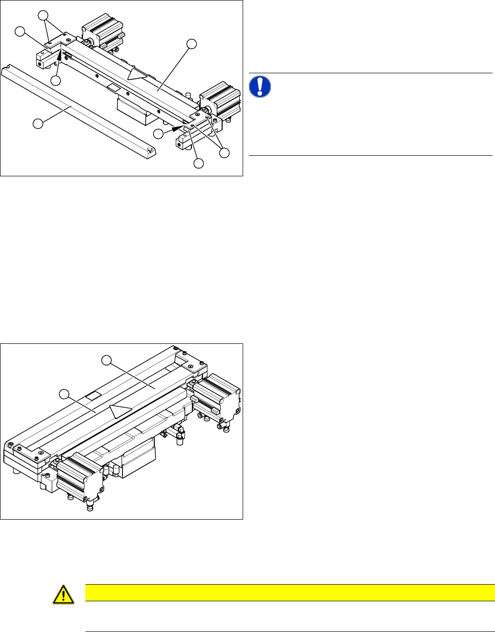
3.9.7 Replacing the Cutter Blades Cutter
Service Manual SIPLACE X Series 225
► Insert the dismantled wiper unit (3) and the downholders back in and tighten loosely with the four
hexagon socket-head screws (4).
► Push the spacers (with inserted feeler gauges) as far as possible in the direction of the moveable
blade. The maximum permissible gap is 1.0 mm.
► Now tighten the four screws (4) crosswise at the downholder (observe torque).
► Remove the two feeler gauges.
► Insert the new stationary blade (5) in the correct position and screw tight.
Final Work:
If the gap is correct:
► Fit the baffle plate and cover plate. Make sure that the edges are parallel.
► Remove the clamps form the cutter/ remove the cutter from the assembly plate.
Cutter (using example of X series)
► Place a feeler gauge (0.5 - 1.0 mm thickness) on the
left and right, between the spacer and the front of the
moveable blade (1).
► Place the previously removed holding-down device
(2) onto the new spacers.
NOTICE!
Holding-down device
The holding-down devices with function status 03 are de-
signed for use with cutters of function status -04 (= with
tape deflector).
1
2
4
1
5
4
3
2
Cutter (using example of X series)
► Use a feeler gauge to check the gap between the
tape deflector (1) and the moveable blade (2), along
the entire length and width of the blade.
⇨ The 0.05 mm feeler gauge should fit through the
gap.
⇨ The 0.25 mm feeler gauge should not fit through
the gap.
If the gap is not correct, check:
▪ Whether the wrong holding-down device has been in-
stalled (with function status < 03)
▪ The holding-down devices are those designed for
cutters with function status -04 (= with tape deflector)
▪ Whether the blades, tape deflector etc. were cleaned
before installation
1
2
CAUTION
Check how the cables are run!
Make sure that the cables and hoses are not pinched or subjected to excess strain.
Service Work
X-Series Component Trolley 3.10.1 Replacing the Fixed/Guide Castors [00341918-xx]
226 Service Manual SIPLACE X Series
► Further installation is performed by following the above instructions in the reverse order.
See also
3.9.2 Replacing the Cutter [03052900-xx] on the X-Series COT Insert [ ➙ 213]
3.10
3.10 X-Series Component Trolley
X-Series Component Trolley
3.10.1
3.10.1 Replacing the Fixed/Guide Castors [00341918-xx]
Replacing the Fixed/Guide Castors [00341918-xx]
Parts, equipment and tools
▪ Fixed castor [00341918-xx] or
Guide castor [03004958-xx]
▪ Second person
Removal/Installation
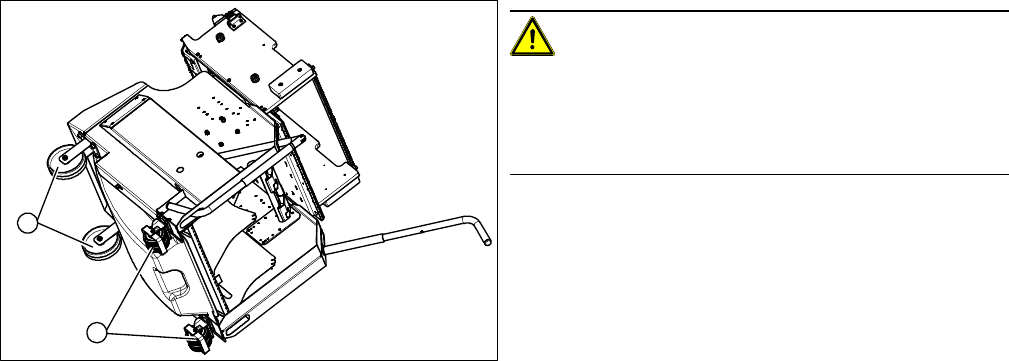
CAUTION!
Heavy machine part!
The component trolley must be placed on one side in or-
der to remove the fixed/guide castors. You will need two
people to perform this task.
► Move the component trolley out of the machine.
► Place the component trolley on its side, on a suitable
surface.
► Loosen the fastening screw on the fixed (1) or guide
castor (2) to be replaced.
► Insert the new fixed or guide castor.
► Stand the component trolley on its wheels again.
1
2
Service Work
3.10.2 Replacing the Locking Latch [03069205-xx] X-Series Component Trolley
Service Manual SIPLACE X Series 227
3.10.2
3.10.2 Replacing the Locking Latch [03069205-xx]
Replacing the Locking Latch [03069205-xx]
Parts, equipment and tools
▪ Single locking latch [03069205-xx]
▪ Tension spring [03010352-xx]
▪ Cover plate for locking strip [03077142-xx]
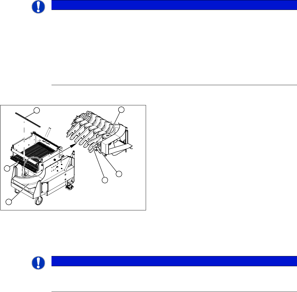
Overview
Removal/installation
► Remove the waste tape container (1) and empty it.
► Refit the waste tape container. This makes sure that any parts which fall down are not lost.
► Loosen the screws fastening the cover plate locking rail [03077142-xx] (2). Use a suitable Phillips
screwdriver, to avoid damaging the screws.
NOTICE
Component trolley X/SX series
Component trolleys from the X series (S) and SX series require a locking latch for each feeder
track.
► X series (S), SX4: feeder lock [03023777-xx] with 40 locking latches
(1x per component trolley X series (S)/SX4)
► Feeder lock [03057284-xx] with 30 locking latches
(1x per 30 track, 2x per 60 track component trolley SX1/SX2)
⇨ The feeder lock can also be completely dismantled from the component trolley and re-
placed.
1. Waste tape container
2. Cover
3. Position of complete feeder locking mechanism
4. Locking latch
5. Tension spring
6. Pressure plate
4
6
5
1
3
2
NOTICE
Tape waste container
You can use the waste tape container as a surface on which to place small parts e.g. tension
springs, locking latches etc.