00194440-10_SM_X-Series_Customer_en.pdf - 第231页
Service Work 3.10.6 Replacing the Actuator/Protective Bracket X-Series Compon ent Trolley Service Manual SIPLACE X Series 231 3.10.6 3 . 1 0 . 6 R e p la c in g t h e A c t u a t o r / P r o t e c t iv e B r a c k e t Re…
Service Work
X-Series Component Trolley 3.10.5 Replacing the Insert Feeder [03002898-xx]
230 Service Manual SIPLACE X Series
3.10.5
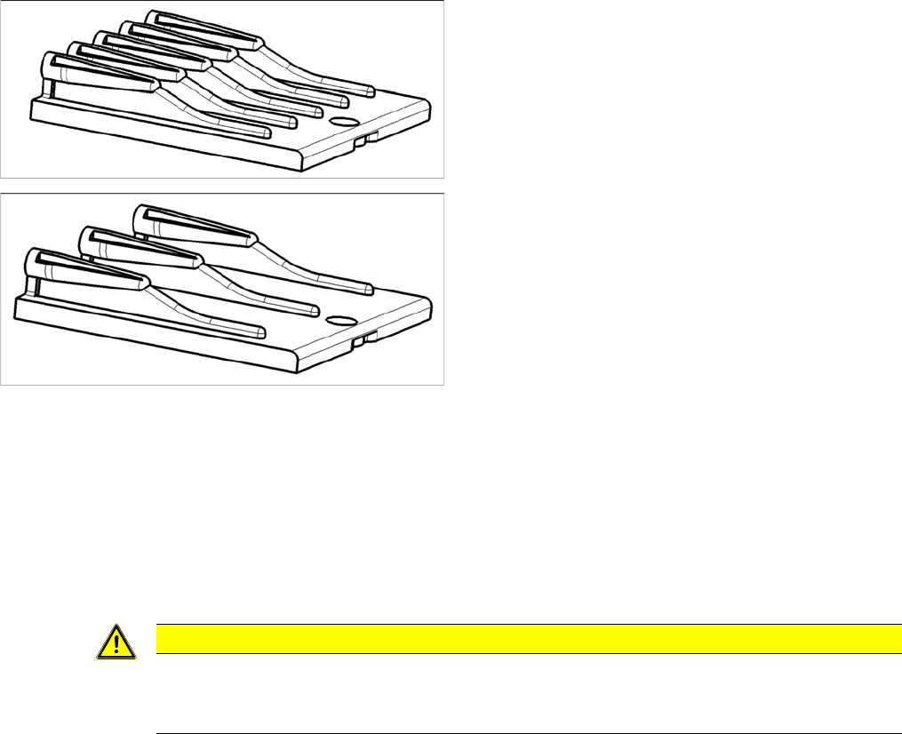
3.10.5 Replacing the Insert Feeder [03002898-xx]
Replacing the Insert Feeder [03002898-xx]
Parts, equipment and tools
Select the right insert feeder:
Removal
► Move the component trolley out of the machine.
► Loosen the screw fastening the guide profile and remove the guide profile.
Installation
► Follow the removal instructions in reverse order for installation. Also observe the following instruc-
tions:
Insert feeder [03002898-xx]
Suitable for:
▪ X-Series component trolley
▪ Component trolley SX1/SX2 (30 or 60 tracks)
▪ Manual table X-Series S
Insert feeder [03085635-xx]
Suitable for:
▪ Manual table DX series
CAUTION
Installation instructions
► Make sure that the insert is aligned properly with the guidance behind it. You must be able
to push feeder modules into the feeder location without edge interference.
Service Work
3.10.6 Replacing the Actuator/Protective Bracket X-Series Component Trolley
Service Manual SIPLACE X Series 231
3.10.6
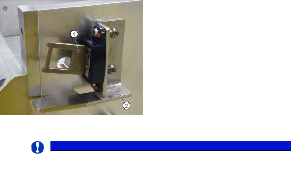
3.10.6 Replacing the Actuator/Protective Bracket
Replacing the Actuator/Protective Bracket
Parts, equipment and tools
▪ Torque wrench T20 with drilled hole (for screw ISO 7380-TX with pin - M4)
▪ Actuator AZ335 Schmersal [03013488-xx]
▪ Protective bracket: holder and protection for actuator [03095447-xx]
Overview
Installation
1. Actuator
2. Protective bracket
NOTICE
Installation instructions
► Tighten the fastening screws for the actuator on the protective bracket with amaximum
torque of 200 Ncm.
► Set the actuator (see "5.5.1 Setting the Actuator on the Component Trolley" [ ➙ 347]).
Service Work
Component Trolley HF R2 3.11.1 Replacing the Fixed/Guide Castors [00341918-xx]
232 Service Manual SIPLACE X Series
3.11
3.11 Component Trolley HF R2
Component Trolley HF R2
3.11.1
3.11.1 Replacing the Fixed/Guide Castors [00341918-xx]
Replacing the Fixed/Guide Castors [00341918-xx]
Parts
▪ Fixed castor (00341918-xx)
▪ Guide castor (03004958-xx]
Removal/installation
3.11.2
3.11.2 Replacing the Cable Tree and ODU Connector [03021249-xx]
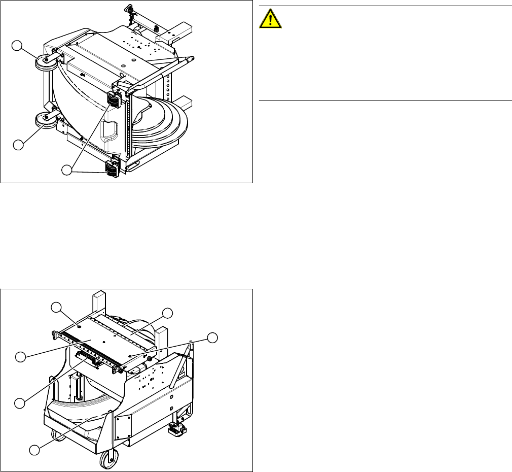
Replacing the Cable Tree and ODU Connector [03021249-xx]
Overview
CAUTION!
Heavy machine part!
The component trolley must be placed on one side in or-
der to remove the fixed/guide castors. The component
changeover table is extremely heavy! You will need 2
people to perform this task.
► Move the component trolley out of the machine.
► Place the component trolley on its side, on a suitable
surface.
► Loosen the fastening screw on the fixed (1) or guide
castor (2) to be replaced.
► Insert the new fixed/guide castor.
► Stand the component trolley on its wheels again.
1
2
1
1. ODU connector with cable tree
2. Feeder Controller Unit
► Move the component trolley out of the machine.
► Loosen the two screws (3) fastening the table plate
(4).
► Remove the waste tape container (5).
► Remove the guidance rods from the height adjust-
ment system.
► Fix the table plate in its highest position. This will help
you to reach the cables more easily.
► Disconnect the ground cable from the frame and from
the component trolley table.
3
5
1
4
3
2