00194440-10_SM_X-Series_Customer_en.pdf - 第234页
Service Work Component Trolley HF R2 3.11.4 Replacing the Feeder Control Unit [03002 179] 234 Service Manua l SIPLACE X Series 3.11.4 3 . 1 1 . 4 R e p la c in g t h e F e e d e r C o n t r o l U n it [ 0 3 0 0 2 1 7 9 ]…
Service Work
3.11.3 Replacing the Table Plate [03020457-xx] Component Trolley HF R2
Service Manual SIPLACE X Series 233
Removal/installation
► Thread the connection cables for the new ODU connector through the hole provided.
► Reconnect the feeder control unit to the electrical system.
► Reconnect the compressed air system and the ground cable.
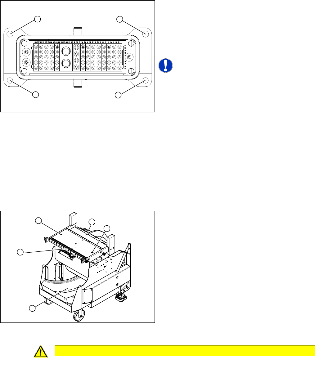
► Fasten the ODU connector with the fitting screws (1) at the top and with the fastening screws (2) at
the bottom.
3.11.3
3.11.3 Replacing the Table Plate [03020457-xx]
Replacing the Table Plate [03020457-xx]
Removal/installation
► Lift the table plate out of the component trolley.
► Lift the new table plate into the component trolley.
► Reconnect the compressed air system and the ground cable.
► Fit the table plate with the two fastening screws and the guidance rods.
Secure the two fastening screws with Loctite 243.
► Loosen the top fitting screws (1) on the ODU connec-
tor.
► Loosen the bottom fastening screws (2) and remove
the ODU connector.
► Disconnect the connection cable from the back of the
feeder control unit.
NOTICE!
The cable for the option "Splice Detection" is already in-
tegrated into the cable tree and is run in a bundle under
the table.
► Disconnect from the compressed air system.
1
1
2
2
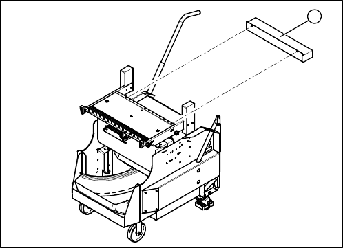
► Move the component trolley out of the machine.
► Remove the waste tape container (4).
► Dismantle the feeder control unit (3).
► Remove the two screws (1) fastening the guide rods
to the table plate (2).
► Remove the guidance rods from the height adjust-
ment system.
► Unplug the ground cable and the compressed air sys-
tem from the underside of the table.
1
3
4
1
2
CAUTION
Heavy machine part!
The table plate is heavy (approx. 29 kg). You will need to enlist the help of a second strong
person to help you lift it out.
Service Work
Component Trolley HF R2 3.11.4 Replacing the Feeder Control Unit [03002179]
234 Service Manual SIPLACE X Series
3.11.4
3.11.4 Replacing the Feeder Control Unit [03002179]
Replacing the Feeder Control Unit [03002179]
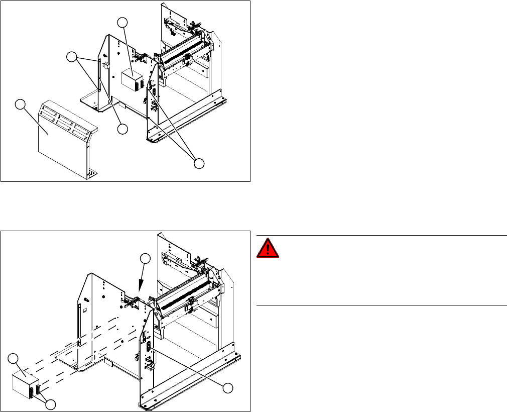
Overview
1. Feeder control unit (FCU)
► Move the component trolley out of the machine.
► Unplug the connection cable from the back of the
FCU.
► Loosen the fastening screws.
► Fit the new FCU and reconnect to the electrical sys-
tem.
1
Service Work
3.12.1 Replacing the Power Pack [03025938-XX] Docking Station for X-Series Component Trolley
Service Manual SIPLACE X Series 235
3.12
3.12 Docking Station for X-Series Component Trolley
Docking Station for X-Series Component Trolley
3.12.1
3.12.1 Replacing the Power Pack [03025938-XX]
Replacing the Power Pack [03025938-XX]
Parts, equipment and tools
▪ Circuit diagram folder for your machine
Overview
Removal/installation
► Reconnect the connection leads and install the new power pack.
► Connect the power pack connection cable and press the ON/OFF button to switch on.
► Set the output voltage of the power pack to 26.8 V (+/- 0.5 V) at terminals nine and twelve.
► Refit the cover.
1. Cover
2. Bar for clamping the cover
3. Fastening screws
4. Power pack
► Loosen the four screws (3) fastening the cover (1).
The cover is clamped in place with the help of the bar
(2).
► Pull the cover out of the docking station.
► Take care not to damage the earth connection.
4
3
1
3
2
DANGER!
Switch off the voltage supply
Press the ON/OFF button (1) to switch off, and discon-
nect the power supply.
► Loosen the four screws (2) fastening the power pack
(3) on the inside of the docking station.
► Label the connection leads and disconnect these
from the terminal strip (4).
4
3
1
2