00194440-10_SM_X-Series_Customer_en.pdf - 第241页
Service Work 3.12.7 Replacing the Feeder Control Unit (FCU) [03059623-xx] Docking Station for X-Series Component Trolley Service Manual SIPLACE X Series 241 3.12.7 3 . 1 2 . 7 R e p la c in g t h e F e e d e r C o n t r …
Service Work
Docking Station for X-Series Component Trolley 3.12.6 Replacing the 40-Fold Feeder Unlock Device [03011582-xx]
240 Service Manual SIPLACE X Series
Installation
► Loosely screw in the new position end switch.
► Run the connection cable to the connector.
► Reconnect the connection cable and close the connector casing.
► Align the position end switch so that the locking lever actuator switches properly.
► Tighten the fastening screws.
► Connect the power pack connection cable and press the ON/OFF button to switch on.
► Check the position end switch function, by trying out the locking procedure.
3.12.6
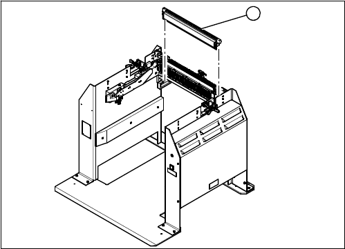
3.12.6 Replacing the 40-Fold Feeder Unlock Device [03011582-xx]
Replacing the 40-Fold Feeder Unlock Device [03011582-xx]
Parts, equipment and tools
▪ Feeder unlocking device 40-fold [03011582-XX]
Overview
Removal/installation
The 40-fold feeder unlock device is the same assembly used in the COT insert. The service work is iden-
tical with the procedure used for the COT insert. All necessary service work is described there.
See also
3.7.3 Replacing the 40-Fold Feeder Unlock Device [03011582-xx] [ ➙ 198]
1. 40 fold feeder unlock device
1
Service Work
3.12.7 Replacing the Feeder Control Unit (FCU) [03059623-xx] Docking Station for X-Series Component Trolley
Service Manual SIPLACE X Series 241
3.12.7
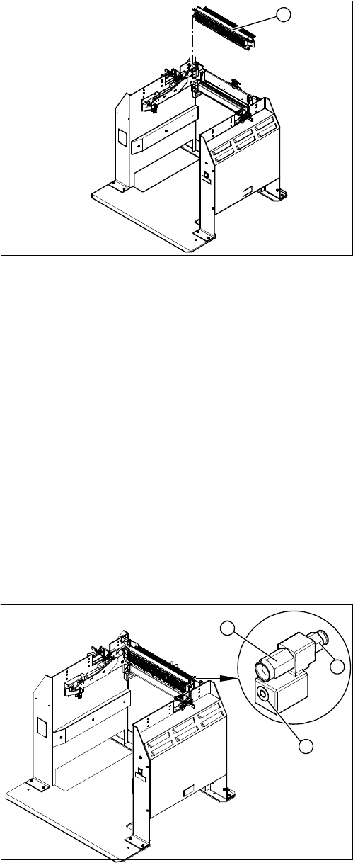
3.12.7 Replacing the Feeder Control Unit (FCU) [03059623-xx]
Replacing the Feeder Control Unit (FCU) [03059623-xx]
Parts, equipment and tools
▪ X-FCU, X-Series [03059623-xx]
Overview
Removal/installation
Removal and installation is identical to that for the COT insert.
See also
3.7.2 Replacing the X Series Feeder Control Unit (FCU) [03020068-xx] [ ➙ 197]
3.12.8
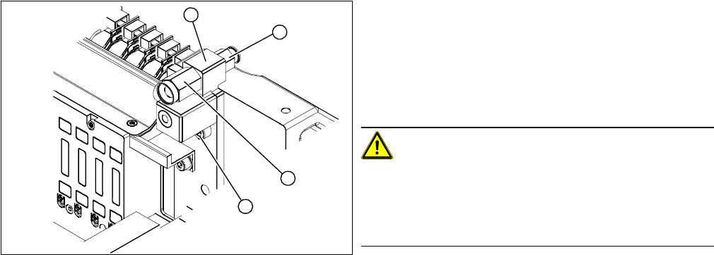
3.12.8 Replacing the Complete Coupling - Earthing and Compressed Air for the Bulk Case
Replacing the Complete Coupling - Earthing and Compressed Air for the Bulk Case
Parts, Equipment and Tools
You can either replace the individual coupling socket or the complete coupling unit for earthing and com-
pressed air.
▪ Coupling socket for compressed air coupling [03017026-xx]
▪ Coupling assembly for ground and compressed air [03017025-xx]
Overview
1. Feeder Control Unit
1
1. Coupling socket for component trolley compressed
air coupling (bulkcase feeder)
2. Pneumatic connection to pneumatic control valve 5.5
bar
3. Component trolley ground coupling (bulkcase feeder)
3
1
2
Service Work
Docking Station for X-Series Component Trolley 3.12.8 Replacing the Complete Coupling - Earthing and Compressed Air for the
242 Service Manual SIPLACE X Series
Removal/Installation
Individual replacement of coupling socket for compressed air coupling
► Unplug the compressed air connection.
► Use an open-end wrench to unscrew the coupling socket from its mount .
► Screw in the new coupling socket and connect the compressed air supply.
► Switch on the compressed air supply.
► Check the set pressure of 5.5 bar at the pressure control valve (located at the back).
Replacing the complete coupling for earthing and compressed air
► Unplug the compressed air connection.
► Loosen the fastening screw and remove the complete unit.
► Fit the new assembly and reconnect the compressed air supply.
► Switch on the compressed air supply.
► Check the set pressure of 5.5 bar at the pressure control valve (located at the back).
1. Fastening the complete coupling (earthing and com-
pressed air)
2. Coupling socket for compressed air coupling
3. Mount
4. Pneumatic connection to pressure control valve 5.5
bar at the back
CAUTION!
Risk of injury from compressed air!
Risk of injury when disconnecting pressurized com-
pressed air lines.
Switch off the compressed air supply.
3
2
4
1