00194440-10_SM_X-Series_Customer_en.pdf - 第255页
Settings 5.1.1 Travel Ranges and Speed M onitoring at the X3 (A363) Gantry Settings Service Manual SIPLACE X Series 255 5 5 S e t t in g s Settings 5.1 5 . 1 G a n t r y S e t t in g s Gantry Settings 5.1.1 5 . 1 . 1 T r…
Measuring Equipment and Tools
Component Sensor Protective Cap (CPP) [03080984-xx] 4.1.1 Scope of Delivery
254 Service Manual SIPLACE X Series
4.18
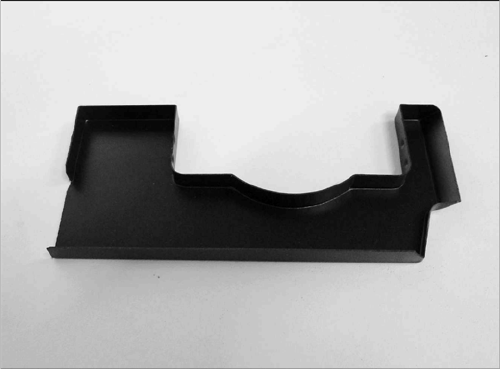
4.18 Component Sensor Protective Cap (CPP) [03080984-xx]
Component Sensor Protective Cap (CPP) [03080984-xx]
Component sensor protective cap for the CPP head
[03080984-xx]
Settings
5.1.1 Travel Ranges and Speed Monitoring at the X3 (A363) Gantry Settings
Service Manual SIPLACE X Series 255
5
5 Settings
Settings
5.1
5.1 Gantry Settings
Gantry Settings
5.1.1
5.1.1 Travel Ranges and Speed Monitoring at the X3 (A363)
Travel Ranges and Speed Monitoring at the X3 (A363)
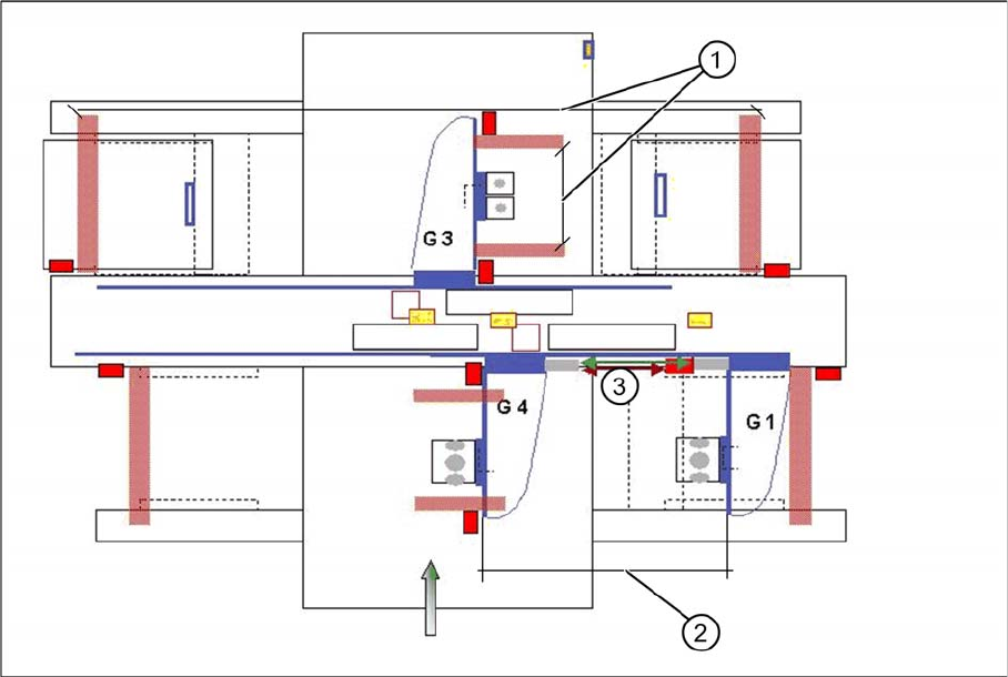
The travel range of the X and Y axes will be determined automatically with the SITEST program. This
means that during calibration of the travel range of gantry 3 at placement area 2, the respective axis
moves as far as possible into its minimum and maximum position, until both proximity switches switch.
A safety gap before the hardware limit switch is calculated for each individual machine (see travel ranges
HF). For the Y axis of placement area 1, gantry 1 moves just to the minimum position and gantry 4 to
the maximum position.
Travel range X and Y axes of X3 machine
1. The calculation of travel ranges for the X axes at gantries 1/3/4 and of the Y axis at gantry 3 follows
the same procedure as the calculation for HF machines.
2. The travel range for the Y axes are calculated partly. This means that the Y axis of gantry 1 moves
into the minimum position and the Y axis of gantry 4 moves into the maximum position. As a result:
maximum position gantry 1 = maximum position gantry 4 - 480mm (gantry width) - 20mm safety
space. (In X4 machines, the travel ranges are set accordingly for gantry 2) Minimum position
gantry 4 = minimum position gantry 1 + 480 mm (gantry width) + 20 mm safety distance. (In X4 ma-
chines, the travel ranges are set accordingly for gantry 3)
3. Safety space approx. 20mm
See also
5.1.5 Anticrash board [ ➙ 262]
Settings
Gantry Settings 5.1.1 Travel Ranges and Speed Monitoring at the X3 (A363)
256 Service Manual SIPLACE X Series
5.1.1.1
5.1.1.1 Setting the Proximity Switch
Setting the Proximity Switch
On each axis are two proximity switches installed, which need a distance about 0.4 mm to the metal ac-
tuator. The metal actuator are installed on the left and right side from the incremental scale. Adjust cor-
rectly the distance with a distance gauge of 0.4 mm. After this adjustment calibrate the travel range for
the respective axis with the SITEST program.
5.1.1.2
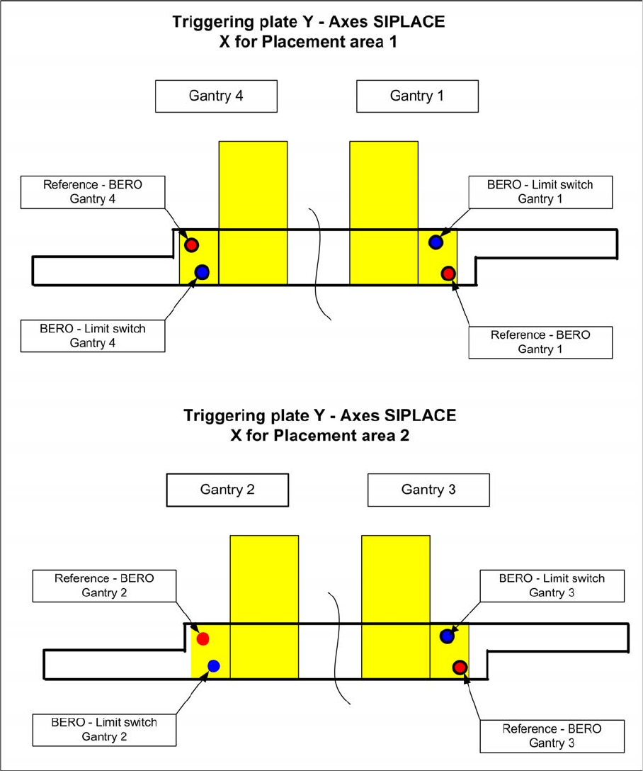
5.1.1.2 Description of the Y Axis Proximity Switches
Description of the Y Axis Proximity Switches
Positions of the proximity switches, depending on the gantries