00194440-10_SM_X-Series_Customer_en.pdf - 第258页
Settings Gantry Settings 5.1.3 Travel Ranges and Speed Monitoring 258 Service Manua l SIPLACE X Series 5.1.3 5 . 1 . 3 T r a v e l R a n g e s a n d S p e e d M o n it o r in g Travel Ranges and Speed Monitoring The trav…
Settings
5.1.2 Travel Ranges and Speed Monitoring (A364) Gantry Settings
Service Manual SIPLACE X Series 257
5.1.2
5.1.2 Travel Ranges and Speed Monitoring (A364)
Travel Ranges and Speed Monitoring (A364)
The travel range of the X and Y axes will be determined automatically with the SITEST program.
This means that, during travel range calibration, the axis concerned moves as far as possible towards
the minimum or maximum position, until the set axis card target value is no longer reached. It is then
assumed that the hardware limit switch (buffer) has been reached. In a time window of approx. 10 ms,
the greatest actual value achieved is taken to calculate the travel range.
To guarantee an appropriate safety gap before the hardware end switch is touched, a certain distance
is deducted from the set travel range. This enables the axis to brake in time, even when errors occur.
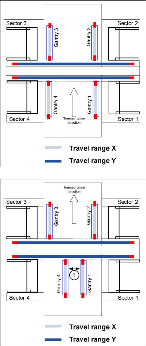
Travel range for X and Y axes (D4 and X4 shown here)
The end of the X axis travel range is + or - 0.5 mm before
the software limit switch, which is 1.5 mm before the buff-
er. A safety distance of 2.0 mm to the buffer is adequate,
if the X axis moves into this area with excessive speed.
The end of the Y axis travel range is + or - 2.0 mm before
the software limit switch. The Y axis travel range for a
particular placement area is monitored in one direction by
the software limit switch and a buffer. In the other direc-
tion, there is a permanent exchange of communication
between the axes and their positions, via the SPI Bus
(see description of the anticrash function).
Travel range for X and Y axes (D4 and X4 shown here)
1. During travel range calibration, the X axis moves as
far as possible towards the minimum or maximum po-
sition, until it touches the bumper.
The travel range is calculated, taking into account a
safety distance.
2. In placement areas 1 and 2, gantry 1/2 moves to the
minimum position and gantry 4/3 to the maximum po-
sition, for calculation of the Y axis travel range .
3. Safety distance between the gantries during place-
ment: minimum 4mm.
Settings
Gantry Settings 5.1.3 Travel Ranges and Speed Monitoring
258 Service Manual SIPLACE X Series
5.1.3
5.1.3 Travel Ranges and Speed Monitoring
Travel Ranges and Speed Monitoring
The travel range of the X and Y axes will be determined during machine calibration.
This means that, during travel range calibration, the axis concerned moves as far as possible towards
the minimum or maximum position, until the set axis card target value is no longer reached. It is then
assumed that the hardware limit switch (buffer) has been reached. In a time window of approx. 10 ms,
the greatest actual value achieved is taken to calculate the travel range.
To guarantee an appropriate safety gap before the hardware end switch is touched, a certain distance
is deducted from the set travel range. This enables the axis to brake in time, even when errors occur.
The X axis moves to the left and right buffer and measures their positions with a safety distance of
2.0 mm. The SW also deducts a value of 0.5 mm from the maximum or minim travel path.
The Y axis moves to its minimum position (gantry 1/2) or maximum position (gantry 3/4).
The opposite position is calculated
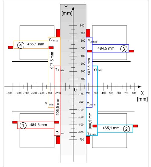
Travel ranges for X and Y axes (X4I)
(1) to (4) = gantry 1 to 4
The end of the X axis travel range is + or - 0.5 mm before
the software limit switch, which is 1.5 mm before the buff-
er. A safety distance of 2.0 mm to the buffer is adequate,
if the X axis moves into this area with excessive speed.
The end of the Y axis travel range is + or - 2.0 mm before
the software limit switch. The Y axis travel range for a
particular placement area is monitored in one direction by
the software limit switch and a buffer. In the other direc-
tion, there is a permanent exchange of communication
between the axes and their positions, via the SPI Bus
(see description of the anticrash function).
Settings
5.1.3 Travel Ranges and Speed Monitoring Gantry Settings
Service Manual SIPLACE X Series 259
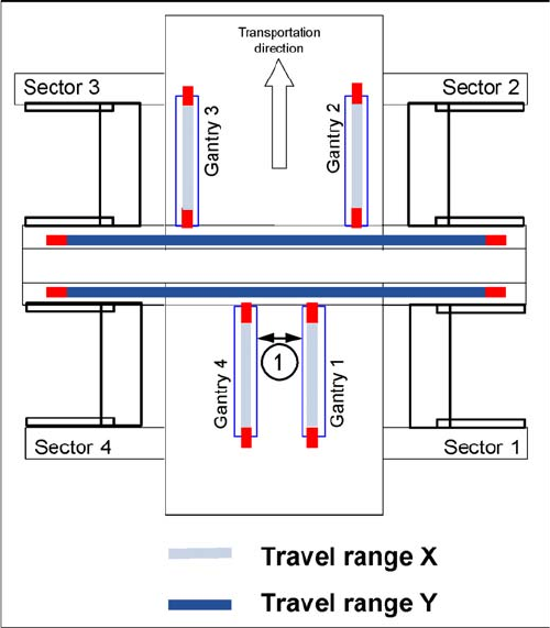
Travel ranges for X and Y axes
1. Safety distance between the gantries during place-
ment: minimum 4mm.
Depending on the placement mode (i-placement or alter-
nating), the gantries will operate in one placement area
fully independently. This means that one gantry does not
need to know the position of the other one.