00194440-10_SM_X-Series_Customer_en.pdf - 第260页
Settings Gantry Settings 5.1.4 Anticrash Function for the A364 Axis Card 260 Service Manua l SIPLACE X Series 5.1.4 5 . 1 . 4 A n t ic r a s h F u n c t io n f o r t h e A 3 6 4 A x is C a r d Anticrash Function for the …
Settings
5.1.3 Travel Ranges and Speed Monitoring Gantry Settings
Service Manual SIPLACE X Series 259
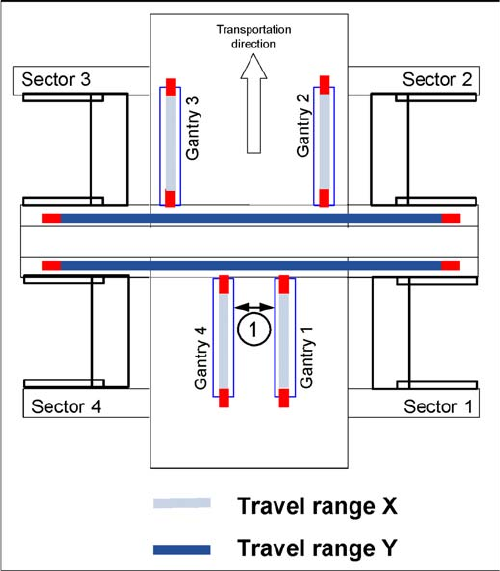
Travel ranges for X and Y axes
1. Safety distance between the gantries during place-
ment: minimum 4mm.
Depending on the placement mode (i-placement or alter-
nating), the gantries will operate in one placement area
fully independently. This means that one gantry does not
need to know the position of the other one.
Settings
Gantry Settings 5.1.4 Anticrash Function for the A364 Axis Card
260 Service Manual SIPLACE X Series
5.1.4
5.1.4 Anticrash Function for the A364 Axis Card
Anticrash Function for the A364 Axis Card
5.1.4.1
5.1.4.1 Anticrash Function for the A364
Anticrash Function for the A364
▪ The anticrash function is no longer provided by the anticrash board but instead by the A364 software
(application 1). This means that the proximity switches used to monitor the travel range and the sen-
sor for monitoring the gantry spacing are no longer required.
▪ Tasks:
– Monitoring the X and Y axis travel ranges
Evaluation of the actual position of the respective axis in the direction of the bumper, based on
the speed.
– Monitoring the distance of both Y axes in a placement area
Evaluation of the actual position of the own gantry and the partner gantry at gantry crash moni-
toring.
– Count error monitoring of the gantry axis
Monitoring incoming count pulses (edge control) over time.
5.1.4.2
5.1.4.2 Anticrash Monitoring for the A364
Anticrash Monitoring for the A364
The anticrash function is activated after the X/Y axes have been referenced. When the gantry axes are
referenced for the first time, anticrash monitoring is not active, which does not matter, due to the low ref-
erence speed.
After this, the bit is set for the anticrash monitoring function and the actual position for the relevant part-
ner gantry is continuously communicated via the SPI Bus.
The following information is exchanged between the Y axes:
▪ Actual position and speed of the own gantry
▪ Status information (reference state, anticrash monitoring state ).
5.1.4.3
5.1.4.3 Error "Gantry Crash"
Error "Gantry Crash"
A “gantry crash” error is established by calculating the position difference and speed difference for both
axes. A gantry crash error is signaled via the axis card and the CAN Bus. The servo is released for both
axes and both need to be referenced again.
5.1.4.4
5.1.4.4 Count Error:
Count Error:
If the axis board detects a "fatal count error", the axis concerned will be released and the anticrash func-
tion disabled. The other axis is informed of this in the status information and will also disable the ant-
icrash function. The released axis now needs to be referenced again.
after which the anticrash function will be re-enabled for both axes.
Settings
5.1.4 Anticrash Function for the A364 Axis Card Gantry Settings
Service Manual SIPLACE X Series 261
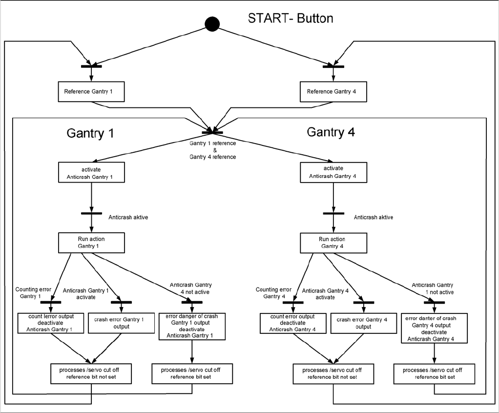
5.1.4.5
5.1.4.5 Anticrash Function
Anticrash Function
Example of the anticrash function sequence in placement area 1