00194440-10_SM_X-Series_Customer_en.pdf - 第264页
Settings Gantry Settings 5.1.5 Anticrash board 264 Service Manua l SIPLACE X Series 5.1.5.3 5 . 1 . 5 . 3 C h e c k in g t h e D is t a n c e S e n s o r F u n c t io n Checking the Distance Sensor Function Preparation ►…
Settings
5.1.5 Anticrash board Gantry Settings
Service Manual SIPLACE X Series 263
5.1.5.1
5.1.5.1 Setting the Sensitivity of the Distance Sensor
Setting the Sensitivity of the Distance Sensor
5.1.5.2
5.1.5.2 Calibrating the Anticrash Board
Calibrating the Anticrash Board
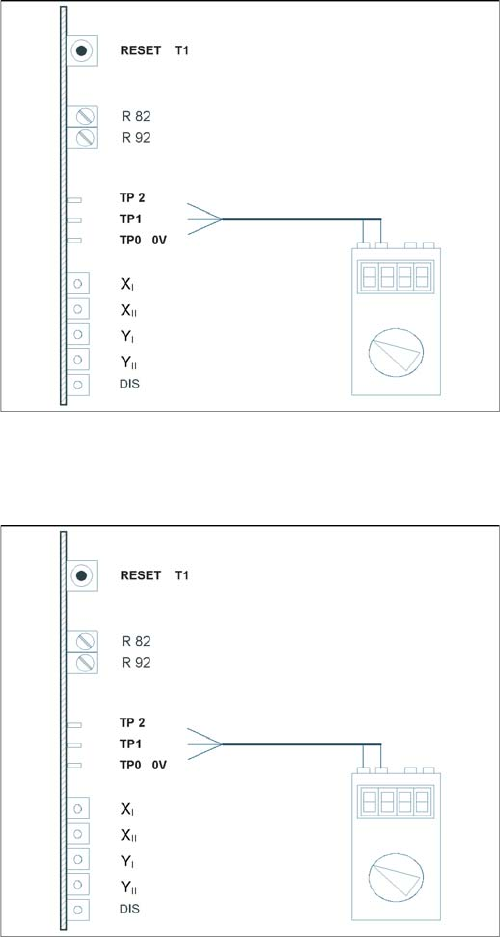
Test setup of anticrash board
► Connect the digital multimeter to the anticrash board
TP 0 (0V) and TP 1 (signal).
► Push the two gantries together.
► Use the adjustment screw to set the voltage on the
distance sensor to 6V - +/- 0.1 V.
► Push the two gantries to a distance of 100 mm.
(elastomeric spring up to countersurface).
► The voltage should be approx. 2V.
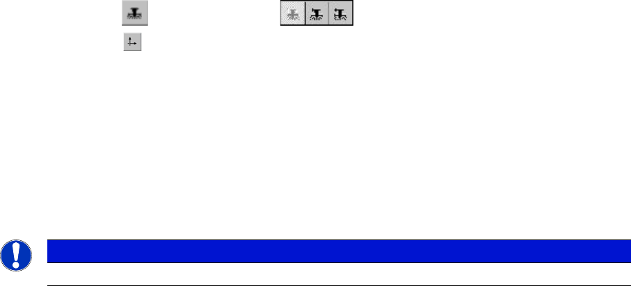
Test setup of anticrash board
► Connect the digital multimeter to the anticrash board
at pin TP2 (signal) and at pin TP0 (0V).
► Push the two gantries together.
► Use the potentiometer R82 to set the voltage to 0V-
+/- 0.05 V.
► Push the two gantries together, to a distance of 100
mm +/- 1 mm.
► Use the potentiometer R92 to set the voltage to 0V-
+/- 0.05 V.
► Check the 0V setting again.
► If the value deviates, you will need to calibrate again.
Settings
Gantry Settings 5.1.5 Anticrash board
264 Service Manual SIPLACE X Series
5.1.5.3
5.1.5.3 Checking the Distance Sensor Function
Checking the Distance Sensor Function
Preparation
► Perform a complete reference run.
Test for placement area 1
► Fasten a sheet of paper to the center of the machine in placement area 1, level with the distance
sensor.
SITEST:
► Select "Gantry" ==> "Choose gantry" ==>
"Axis functions" ==> "Y axis" ==> "Position axis"
==> "Edit values and accept for the target position = 1 300.000 digits".
► Press the START button.
► The axis will stop at the obstacle. The distance sensor has triggered.
► Press the EMERGENCY STOP button and remove the obstacle.
► Press the RESET button on the anticrash board.
► Release the EMERGENCY STOP button and press the START button.
► Perform a reference run for the gantry.
► Perform a test for placement area 2 following the same procedure.
NOTICE
Select "gantry3" for placement area 2. Edit and accept a target position of 600.000 digits
Settings
5.1.6 Mechanical Adjustment of the Incremental Encoder Gantry Settings
Service Manual SIPLACE X Series 265
5.1.5.4
5.1.5.4 Checking the Function of the Anticrash Board
Checking the Function of the Anticrash Board
Preparation
► Perform a complete reference run.
Testing the Proximity Switch on the Gantry
► Press the EMERGENCY STOP button.
► Unplug the relevant connector from the proximity switch.
► Release the EMERGENCY STOP button.
► Press the START button.
► Select the corresponding X or Y axis for the disconnected proximity switch.
SITEST:
► Select "Gantry" ==> "Choose gantry" ==> "Axis functions" ==> "Choose axis"
==> "Dynamic axis behavior" ==> "Set the travel path 9
(200.000 digits)".
▪ The anticrash board will trigger.
▪ The selected axis will brake in the relevant direction.
▪ As the anticrash board has triggered, you will see the following error message here:
"Gantry distance insufficient. Protective circuit reacted".
► Press the EMERGENCY STOP button.
► Reconnect the relevant proximity switch.
► Press the RESET button on the anticrash board.
► Release the EMERGENCY STOP button.
► Select "Cancel" and press the START button.
► The axis is now back in its normal state.
5.1.6
5.1.6 Mechanical Adjustment of the Incremental Encoder
Mechanical Adjustment of the Incremental Encoder
The incremental encoders (read units) on the X and Y axis are adjusted exactly to the position of the
incremental scale. The two limit marks on the incremental encoder show where the top/bottom positions
of the scale should be. The encoder is also mechanically set to a distance of 0.4 mm +/- 0.1 mm to the
incremental scale.
After this adjustment of the incremental encoder you have to check the zero pulse and track signals.
Correct installation should ensure correct count and zero pulse signals. For troubleshooting purposes
(error analysis and fixing), you will need to measures these signals with the oscilloscope. (See service
manual.)
See also
5.1.7 Track Signals and Zero Pulse [ ➙ 266]
NOTICE
The test is identical for all gantry groups.
NOTICE
To set this distance, use one or more small plastic disks with a total thickness of 0.4 mm.