00194440-10_SM_X-Series_Customer_en.pdf - 第272页
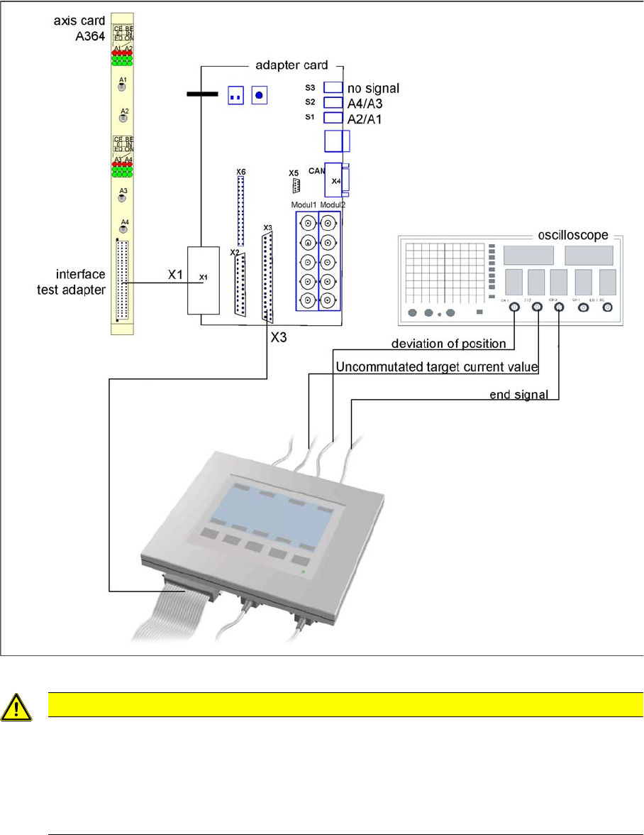
Settings Axis Control 5.2.1 Checking the X Axis Dynamics 272 Service Manua l SIPLACE X Series 5.2.1.2 5 . 2 . 1 . 2 M e a s u r e m e n t S e t u p w it h S A T B o x a n d A 3 6 4 Measurement Setup with SAT Box and A364…
Settings
5.2.1 Checking the X Axis Dynamics Axis Control
Service Manual SIPLACE X Series 271
5.2
5.2 Axis Control
Axis Control
5.2.1
5.2.1 Checking the X Axis Dynamics
Checking the X Axis Dynamics
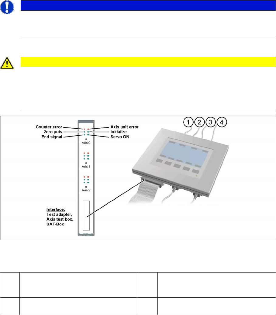
The inspection of dynamics occurs with the following signals:
▪ Deviation of position
▪ Uncommutated target current value
▪ End signal (adapter board, axis in target position)
▪ Actual position = target position signal (axis test box output end position signal)
5.2.1.1
5.2.1.1 Measurement Setup with SAT Box and A363
Measurement Setup with SAT Box and A363
Measurement setup with SAT box
Assignment of output leads for SIPLACE Axis tester for same connection as with axis test box to oscil-
loscope.
Due to the stricter accuracy requirement for a gantry with TwinHead or higher speed for C&P20, the X
and Y axes are operated with different regulation parameters to those used when a gantry is operated
with C&P6/12 (see following diagrams).
NOTICE
Switch machine on 30 mins before start
Before checking the axis dynamics, make sure that the machine has reached its operating tem-
perature. Switch the machine on at least 30 minutes before you begin work.
CAUTION
Checking the dynamics/troubleshooting
When checking the dynamics, it may be sufficient if you check the travel times and overshoot
behavior of the axis with the SIPLACE axis tester display and the values in the settings tables.
However, when checking for errors, you will need to use a suitable oscilloscope for the dynam-
ics analysis.
1 Vnom. output (motor phase current signal I
W): is not needed for checking the X(HF)
dynamics.
3 Position deviation connected at CH1
2 Uncommutated current signal (Vreg), con-
nected to CH2
4 End position signal connected at CH3
Settings
Axis Control 5.2.1 Checking the X Axis Dynamics
272 Service Manual SIPLACE X Series
5.2.1.2
5.2.1.2 Measurement Setup with SAT Box and A364
Measurement Setup with SAT Box and A364
Measurement setup with SAT box
CAUTION
Checking the dynamics/troubleshooting
When checking the dynamics, it may be sufficient if you check the travel times and overshoot
behavior of the axis with the SIPLACE axis tester (SAT) display and the values in the settings
tables.
However, when checking for errors, you will need to use a suitable oscilloscope for the dynam-
ics analysis.
Settings
5.2.1 Checking the X Axis Dynamics Axis Control
Service Manual SIPLACE X Series 273
5.2.1.3
5.2.1.3 Comparison of X Axis Travel Profiles for C&P20A, CPP and TwinHead
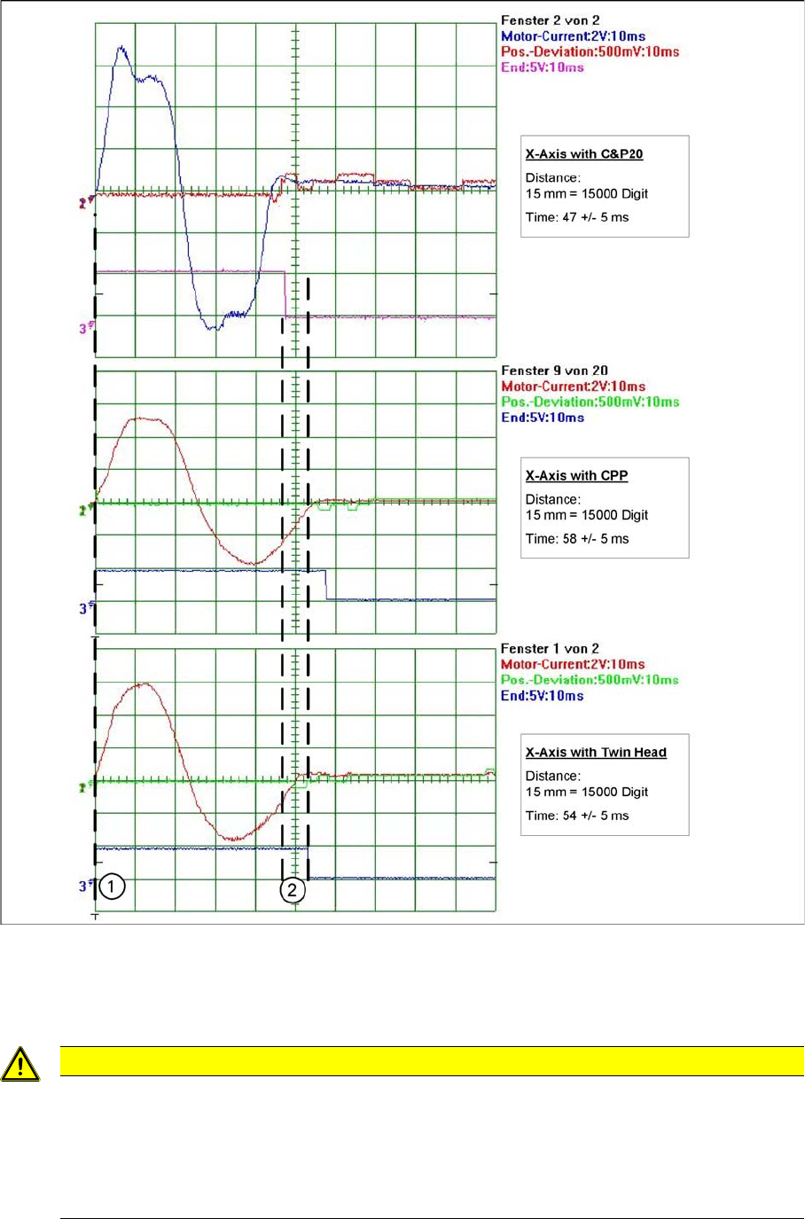
Comparison of X Axis Travel Profiles for C&P20A, CPP and TwinHead
Signal path at 15000 digit travel range of X axis for different head configurations
1. Axis start
2. The end position signal is triggered at different times, depending on the axis records for the 3 head
configurations.
CAUTION
Maximum deviation of position
The maximum deviation of position depends on the placement head:
► C&P20A: 12 µm (digit)
► CPP: 10 μm (digit)
► TwinHead: 5 μm (digit)