00194440-10_SM_X-Series_Customer_en.pdf - 第274页
Settings Axis Control 5.2.1 Checking the X Axis Dynamics 274 Service Manua l SIPLACE X Series 5.2.1.4 5 . 2 . 1 . 4 X A x is T r a v e l T im e T a b le , A c c o r d in g t o P la c e m e n t H e a d s X Axis Travel Tim…
Settings
5.2.1 Checking the X Axis Dynamics Axis Control
Service Manual SIPLACE X Series 273
5.2.1.3
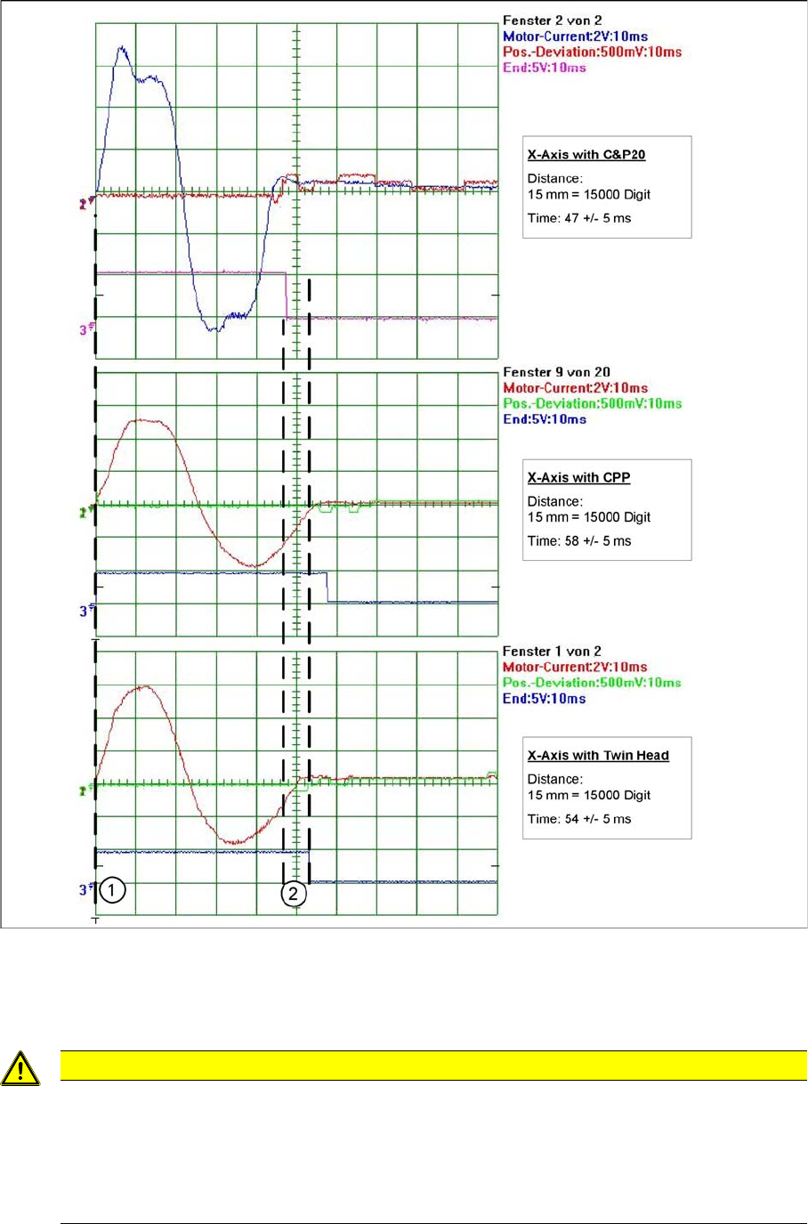
5.2.1.3 Comparison of X Axis Travel Profiles for C&P20A, CPP and TwinHead
Comparison of X Axis Travel Profiles for C&P20A, CPP and TwinHead
Signal path at 15000 digit travel range of X axis for different head configurations
1. Axis start
2. The end position signal is triggered at different times, depending on the axis records for the 3 head
configurations.
CAUTION
Maximum deviation of position
The maximum deviation of position depends on the placement head:
► C&P20A: 12 µm (digit)
► CPP: 10 μm (digit)
► TwinHead: 5 μm (digit)

Settings
Axis Control 5.2.1 Checking the X Axis Dynamics
274 Service Manual SIPLACE X Series
5.2.1.4
5.2.1.4 X Axis Travel Time Table, According to Placement Heads
X Axis Travel Time Table, According to Placement Heads
Travel times for X gantry axis with the various head configurations
* C&P: for SW 603.xx, the X axis target times are approx. 5 ms shorter than those specified above.
Distance /
digit
X gantry axis with C&P20 X gantry axis with DLM2
(C&P6, C&P12)
X gantry axis with TwinHead
Target time /
ms*
Tolerance /
ms
Target time /
ms*
Tolerance /
ms
Target time /
ms
Tolerance /
ms
50018+/-526+/-525+/-5
1000 20 +/-5 29 +/-5 28 +/-5
2000 24 +/-5 35 +/-5 34 +/-5
5000 31 +/-5 47 +/-5 41 +/-5
15000 47 +/-5 58 +/-5 54 +/-5
20000 53 +/-5 64 +/-5 59 +/-5
50000 79 +/-10 87 +/-10 87 +/-10
100000 108 +/-10 126 +/-10 125 +/-10
200000 151 +/-10 174 +/-10 170 +/-10
300000 190 +/-15 213 +/-15 209 +/-15
Settings
5.2.1 Checking the X Axis Dynamics Axis Control
Service Manual SIPLACE X Series 275
5.2.1.5
5.2.1.5 Axis Control Assemblies
Axis Control Assemblies
5.2.1.6
5.2.1.6 Travel Time Table for C&P20A X Axis
Travel Time Table for C&P20A X Axis
Travel times for X gantry axis
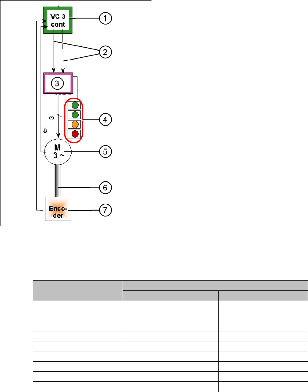
"Axis control" assemblies
The control loop for the X and Y axis consists of the fol-
lowing parts:
▪ Axis card A363 with VC3 controller or A364
▪ Servo board (TDS)
▪ 3 phase AC linear motor
▪ Measurement system (incremental scale and encod-
er (read unit))
To protect the linear motors from overtemperature, all
these motors have an internal temperature sensor.
1. Axis controller board A363 with VC3 controller (VC =
Velocity Commutation) or A 364
2. Control signals I
nom "W"
and I
nom "U"
3. Servo amplifier
4. LEDs on the servo amplifier:
GREEN: Supply voltage switched on
GREEN: Servo enable, if release from axis card is
present.
ORANGE: Display effective current limiting shorter
2.5 s.
RED: Malfunction: overvoltage, overcurrent, over-
temperature or nominal current exceeded, lasting
longer than 2.5 sec.
5. 3-phase AC linear motor for X and Y axes with inte-
grated temperature sensor.
6. Between the motor and incremental encoder there is
a fixed mechanical connection.
7. Incremental encoder: transmits the exact position of
the axis to the axis card. The track signals are the
only feedback signals for the axis control.
The servo board directly controls the linear motor, the in-
termediate circuit voltage is 250 V.
Distance / digit X gantry axis with C&P20A
Target time / ms Tolerance /ms
600 27 +/-5
1000 27 +/-5
2000 27 +/-5
5000 27 +/-5
15000 42 +/-5
20000 48 +/-5
50000 74 +/-5
100000 103 +/-5
200000 146 +/-5