00194440-10_SM_X-Series_Customer_en.pdf - 第277页
Settings 5.2.2 Checking the Y Axis Dynamics Axis Control Service Manual SIPLACE X Series 277 1. Axis start 2. The end position signal is tri ggered at diffe rent times, depe nding on the axis rec ords for th e three head…
Settings
Axis Control 5.2.2 Checking the Y Axis Dynamics
276 Service Manual SIPLACE X Series
5.2.2
5.2.2 Checking the Y Axis Dynamics
Checking the Y Axis Dynamics
5.2.2.1
5.2.2.1 Measurement Setup
Measurement Setup
5.2.2.2
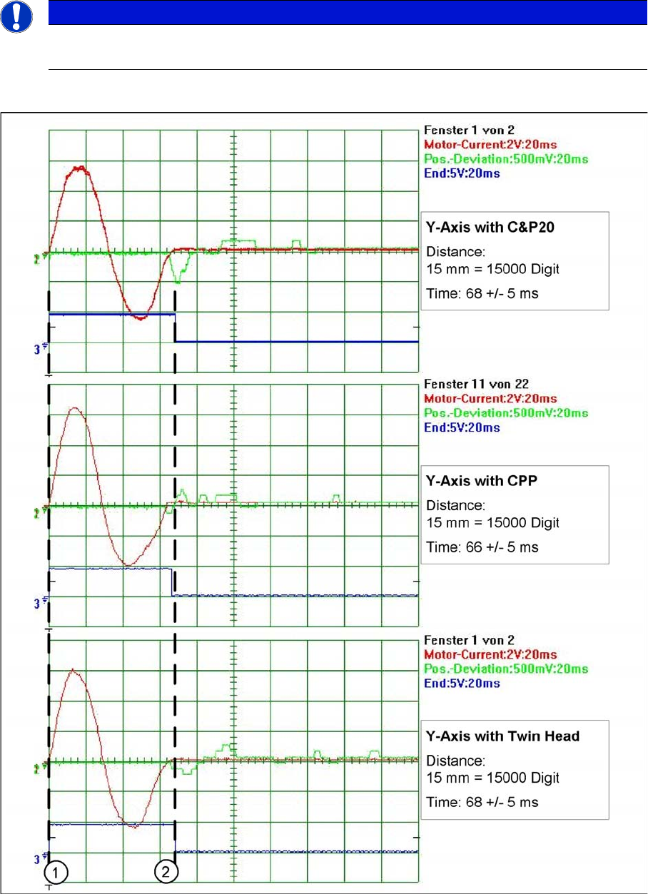
5.2.2.2 Comparison of Y Axis Travel Profiles for C&P20A, CPP and TwinHead
Comparison of Y Axis Travel Profiles for C&P20A, CPP and TwinHead
Signal path at 15000 digit travel range of Y axis for the different head configurations
NOTICE
Same measurement procedure
The measurement procedure follows the same preparations and procedures as for the X axis.
Settings
5.2.2 Checking the Y Axis Dynamics Axis Control
Service Manual SIPLACE X Series 277
1. Axis start
2. The end position signal is triggered at different times, depending on the axis records for the three
head configurations.
5.2.2.3
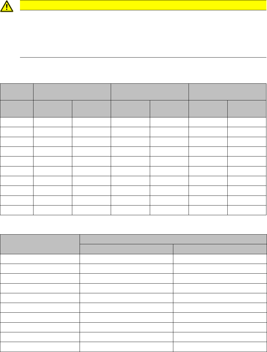
5.2.2.3 Y Axis Travel Time Table, According to Placement Heads
Y Axis Travel Time Table, According to Placement Heads
Y gantry axis travel times for the various head configurations
5.2.2.4
5.2.2.4 Travel Time Table for C&P20A Y Axis
Travel Time Table for C&P20A Y Axis
CAUTION
Maximum deviation of position
The maximum deviation of position depends on the placement head:
► C&P20A: 12 µm (digit)
► CPP: 10 μm (digit)
► TwinHead: 5 μm (digit)
Y gantry axis with C&P20 Y gantry axis with DLM2
(C&P6, C&P12)
Y gantry axis with TwinHead
Distance /
digit
Target time /
ms
Tolerance /
ms
Target time /
ms
Tolerance /
ms
Target time /
ms
Tolerance /
ms
50027+/-538+/-535+/-5
1000 31 +/-5 39 +/-5 40 +/-5
2000 41 +/-5 42 +/-5 46 +/-5
5000 50 +/-5 49 +/-5 53 +/-5
15000 68 +/-5 66 +/-5 68 +/-5
20000 76 +/-5 73 +/-5 76 +/-5
50000 106 +/-10 101 +/-10 108 +/-10
100000 153 +/-10 144 +/-10 147 +/-10
200000 198 +/-10 195 +/-10 199 +/-10
600000 335 +/-15 352 +/-15 357 +/-15
Distance / digit Y gantry axis with C&P20A
Target time / ms Tolerance /ms
600 27 +/- 5
1000 30 +/- 5
2000 31 +/- 5
5000 45 +/- 5
15000 64 +/- 5
20000 71 +/- 5
50000 101 +/- 5
100000 138 +/- 5
200000 175 +/- 5
300000 213 +/- 5
Settings
Axis Control 5.2.3 C&P6/12
278 Service Manual SIPLACE X Series
5.2.3
5.2.3 C&P6/12
C&P6/12
5.2.3.1
5.2.3.1 Overview of Axis Control for Star, Z and DP Axis
Overview of Axis Control for Star, Z and DP Axis
Positioning time for C&P12
Positioning Time for C&P12
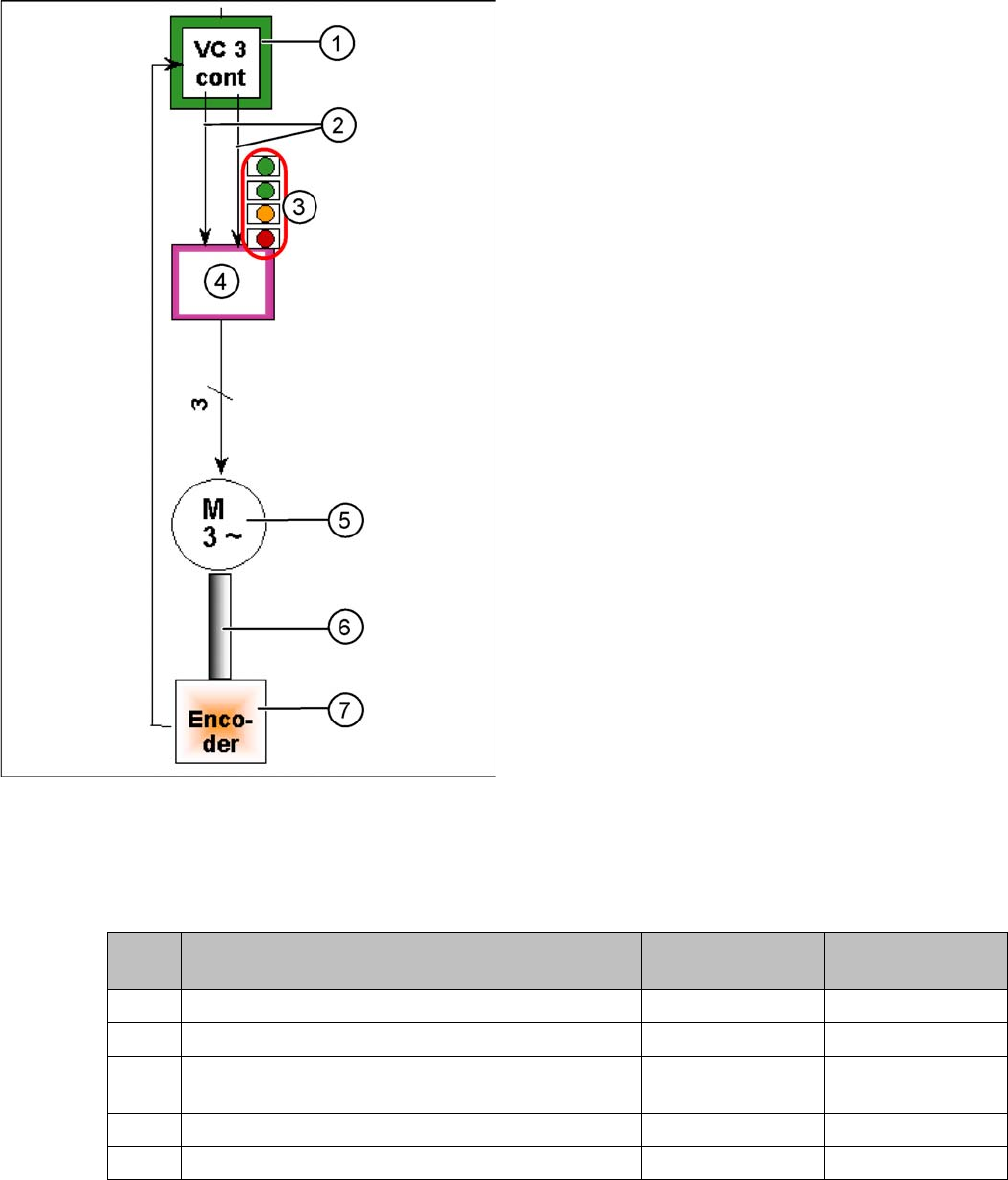
Star axis control system
The closed-loop control system for control of the head
axes consists of the following parts. The differences be-
tween the head axes will be explained later in this chap-
ter.
▪ Axis card A363 with VC3 controller or A364
▪ Servo card (SDS)
▪ Motor
▪ Measurement system (incremental scale and encod-
er (read unit)
1. Axis controller board A363 with VC3 controller (VC =
Velocity Commutation)
2. Control signals I target "W" and I target "U"
3. LEDs on servo amplifier:
4. Servo amplifier
5. 3 phase AC motor.
6. Between the motor and the incremental encoder
there is a fixed mechanical connection.
7. Incremental encoder: transmits the exact position of
the axis to the axis card. (The track signals are the
only feedback signals for the axes).
The servo board controls the motor directly.
Axis Mode/range Standard position-
ing time
Positioning time
DLM3 with SW603
Star Axis continuous run / 1 star step 46 ms +/-3 ms 43ms +/-3ms
Z Absolute, free space / 685 digits 24 ms, -1 ms 21ms, -1ms
Z Light barrier, in calibration tool pocket / approx.
685 digits
24 +/-3 ms 21 +/-3ms
DP 100 digits 13 ms +/-3 ms 13 ms +/-3 ms
DP 3600 digits 43ms +/-3ms 39 ms +/-3 ms