00194440-10_SM_X-Series_Customer_en.pdf - 第28页
Overview of the Modules Electrical System 2.2.1 Axis Units 28 Service Manual SIPLACE X Series 2.2.1.4 2 . 2 . 1 . 4 S e r v o A m p lif ie r T B S . . a n d S D S . . . Servo Amplifier TBS .. and SDS ... Servo am plifier…

Overview of the Modules
2.2.1 Axis Units Electrical System
Service Manual SIPLACE X Series 27
2.2.1.3
2.2.1.3 A364 - Axis Cards for X Machine Types and Head Modularity
A364 - Axis Cards for X Machine Types and Head Modularity
X4 and X4I Assembly 1 Adr. Assembly 2 Adr. Assembly 3 Adr.
Placement area 1
Axis type/gantry X1 0 X4 4 DP1_1 8
Axis type/gantry Y1 1 Y4 5 Free
DP1_2
9
Axis type/gantry S1
Z1_2
2S4
Z4_2
6DP4_1 10
Axis type/gantry Z1_1 3 Z4_1 7 Free
DP4_2
11
Placement area 2
Axis type/gantry X2 16 X3 20 DP2_1 24
Axis type/gantry Y2 17 Y3 21 Free
DP2_2
25
Axis type/gantry S2
Z2_2
18 S3
Z3_2
22 DP3_1 26
Axis type/gantry Z2_1 19 Z3_1 23 Free
DP3_2
27
X3 Assembly 1 Adr. Assembly 2 Adr. Assembly 3 Adr.
Placement area 1
Axis type/gantry X1 0 X4 4 DP1_1 8
Axis type/gantry Y1 1 Y4 5 Free
DP1_2
9
Axis type/gantry S1
Z1_2
2S4
Z4_2
6DP4_1 10
Axis type/gantry Z1_1 3 Z4_1 7 Free
DP4_2
11
Placement area 2
Axis type/gantry 16 X3 20 24
Axis type/gantry 17 Y3 21 25
Axis type/gantry 18 S3
Z3_2
22 DP3_1 26
Axis type/gantry 19 Z3_1 23 Free
DP3_2
27
X2 Assembly 1 Adr. Assembly 2 Adr. Assembly 3 Adr.
Axis type/gantry X1 0 X3 4 DP1_1 8
Axis type/gantry Y1 1 Y3 5 Free
DP1_2
9
Axis type/gantry S1
Z1_2
2S3
Z3_2
6DP3_1 10
Axis type/gantry Z1_1 3 Z3_1 7 Free
DP3_2
11
Overview of the Modules
Electrical System 2.2.1 Axis Units
28 Service Manual SIPLACE X Series
2.2.1.4
2.2.1.4 Servo Amplifier TBS .. and SDS ...
Servo Amplifier TBS .. and SDS ...
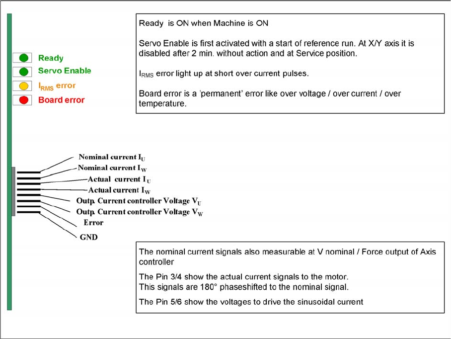
Servo amplifier
The servo amplifiers of type TBS are used for the X/Y and star axes, while the SDS servo amplifier is
used for the Z and DP axes. SDS servo amplifiers can process voltages of up to 60 VDC or 120 VDC,
depending on the input.
These SDS and TBS servo amplifiers can be reset with the servo release switch on the axis controller
board.
All servos have been set to the maximum motor current of the connected drive. This means that the ser-
vo amplifiers need to be used on an axis-specific basis.
Measuring point MP7:
In the event of errors, voltages can be measured at analog output MP7 with the help of the measuring
device, to help you ascertain the cause of the error.
▪ Overvoltage -1 V
▪ Overcurrent -2 V
▪ Overtemperature -3 V
▪ Nominal current exceeded -4 V
Overview of the Modules
2.2.1 Axis Units Electrical System
Service Manual SIPLACE X Series 29
2.2.1.5
2.2.1.5 Overview of Axis Unit
Overview of Axis Unit
2.2.1.6
2.2.1.6 Servo Positions X Series
Servo Positions X Series
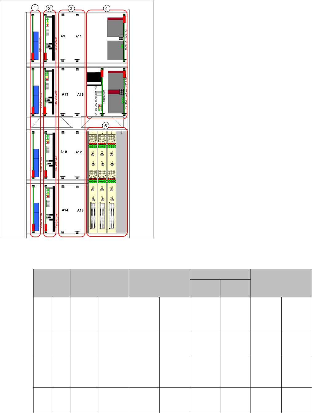
Servo positions
1. Brake boards X/Y
2. Servo amplifier X/Y
3. Head servo positions
4. Power packs, ballast circuit (new power packs with
downwards compatibility)
5. Axis controller boards
Head servo
positions
C&P6/12 C&P20 TwinHead CPP
Segment
2
Segment
1
A9 A11 SDS
120/
2.5S1-
03
SDS 60/
3Z1-02
SDS 120/
2.5S1-03
SDS 60/
2.5Z1-02
SDS 60/
1Z1-02
SDS 60/
1Z1-02
SDS 120/
2.5S1-03
SDS 120/
1.5Z2-01
A13 A15 -SDS 60/
1D1-02
- DC/DC
converter
DP drives
SDS 60/
0.5D1-03
SDS 60/
0.5D1-03
-DC/DC
converter
DP drives
A10 A12 SDS
120/
2.5S1-
03
SDS 60/
3Z1-02
SDS 120/
2.5S1-03
SDS 60/
2.5Z1-02
SDS 60/
1Z1-02
SDS 60/
1Z1-02
SDS 120/
2.5S1-03
SDS 120/
1.5Z2-01
A14 A16 -SDS 60/
1D1-02
- DC/DC
converter
DP drives
SDS 60/
0.5D1-03
SDS 60/
0.5D1-03
-DC/DC
converter
DP drives