00194440-10_SM_X-Series_Customer_en.pdf - 第283页
Settings 5.2.3 C&P6/12 Axis Control Service Manual SIPLACE X Series 283 Measurement Setup with SAT Box and A364 Measurement setup with SAT box
Settings
Axis Control 5.2.3 C&P6/12
282 Service Manual SIPLACE X Series
Measurement Setup with SAT Box and A363
Measurement setup with SAT box
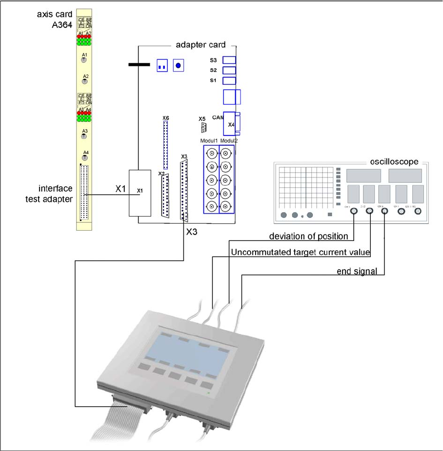
Assignment of output leads by the SIPLACE Axis Tester and connection to the oscilloscope.
1 Vnom. output signal is currently not needed
for checking the HF dynamics.
3 Position deviation connected at CH1
2 Uncommutated current signal (Vreg), con-
nected to CH2
4 End position signal connected at CH3
Settings
5.2.3 C&P6/12 Axis Control
Service Manual SIPLACE X Series 283
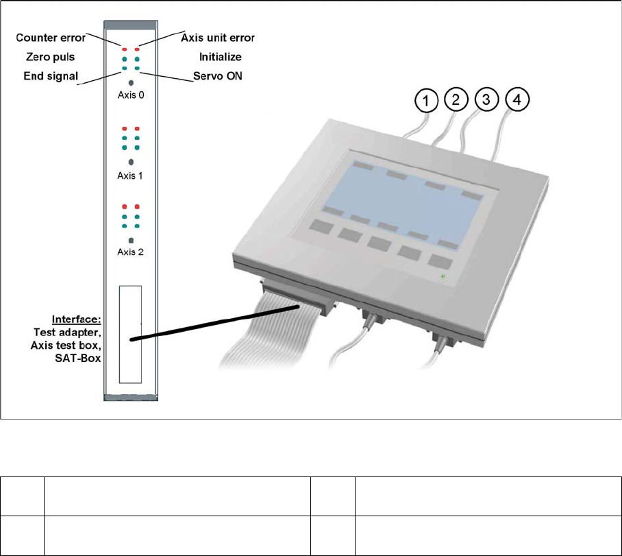
Measurement Setup with SAT Box and A364
Measurement setup with SAT box
Settings
Axis Control 5.2.3 C&P6/12
284 Service Manual SIPLACE X Series
Signal Example with the Vnom. Output
SITEST:
► Select C&P heads ==> Select head ==> Axis functions
==> Select the star axis ==> Star continuous operation ==> Entry: waiting period 500 ms
==> Accept.
► Press the START button if required.
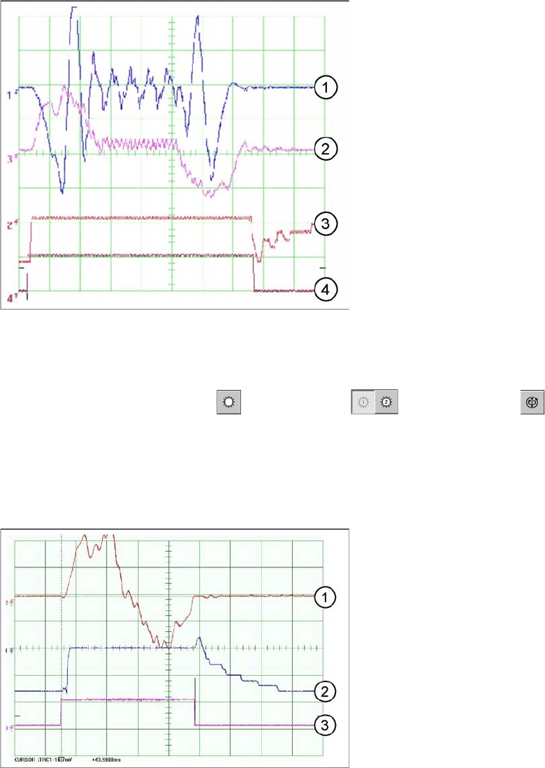
C&P12 - star axis diagram
Dynamic signals for star axis, in example of C&P6
The star axis dynamics are checked in the permanent
star step mode. A motor phase current is emitted at the
Vnominal output of the axis test box.(control signal 1).
The uncommutated current setpoint signal (signal 3)
shows increased friction values for the axis.
1. Control signal (axis test box V nom.)
2. Uncommutated current signal at axis adapter
3. Deviation of position
4. End signal
Star axis travel curves for C&P12
1. Current target value: 2 V/Div
2. Position deviation: 500 mV/Div
3. End signal
Time basis: 10ms/Div
1 step = 30000 digits = 30 degrees