00194440-10_SM_X-Series_Customer_en.pdf - 第285页
Settings 5.2.3 C&P6/12 Axis Control Service Manual SIPLACE X Series 285 C&P6 - star axis diagram Star axis travel curves for C& P6 1. Current target value: 2 V/D iv 2. Position dev iation: 500 mV/Div 3. End s…
Settings
Axis Control 5.2.3 C&P6/12
284 Service Manual SIPLACE X Series
Signal Example with the Vnom. Output
SITEST:
► Select C&P heads ==> Select head ==> Axis functions
==> Select the star axis ==> Star continuous operation ==> Entry: waiting period 500 ms
==> Accept.
► Press the START button if required.
C&P12 - star axis diagram
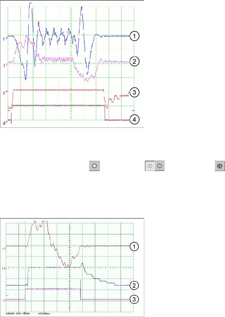
Dynamic signals for star axis, in example of C&P6
The star axis dynamics are checked in the permanent
star step mode. A motor phase current is emitted at the
Vnominal output of the axis test box.(control signal 1).
The uncommutated current setpoint signal (signal 3)
shows increased friction values for the axis.
1. Control signal (axis test box V nom.)
2. Uncommutated current signal at axis adapter
3. Deviation of position
4. End signal
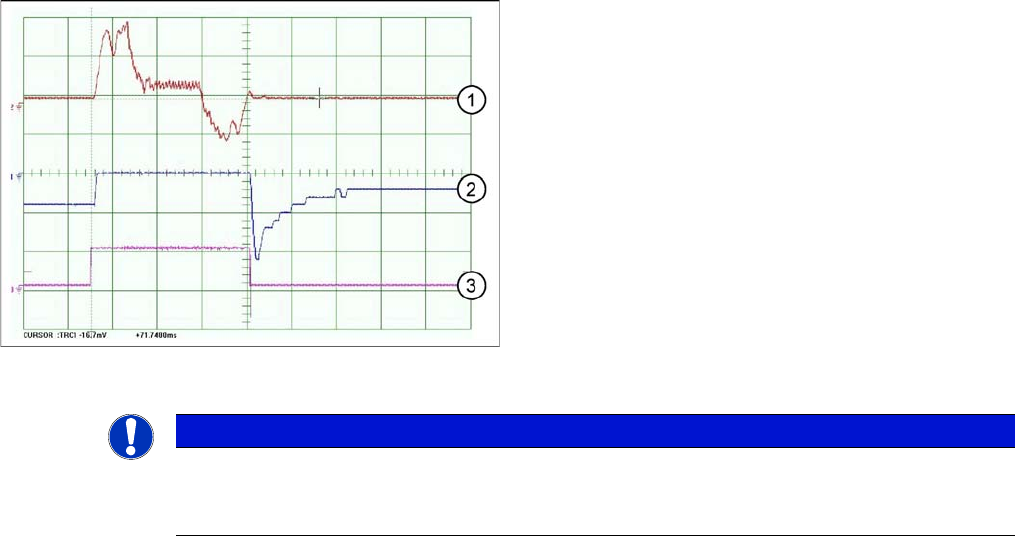
Star axis travel curves for C&P12
1. Current target value: 2 V/Div
2. Position deviation: 500 mV/Div
3. End signal
Time basis: 10ms/Div
1 step = 30000 digits = 30 degrees
Settings
5.2.3 C&P6/12 Axis Control
Service Manual SIPLACE X Series 285
C&P6 - star axis diagram
Star axis travel curves for C&P6
1. Current target value: 2 V/Div
2. Position deviation: 500 mV/Div
3. End signal
Time basis: 10ms/Div
Step: 60000 digits = 60 degrees
NOTICE
Dynamics
If the dynamics are significantly slower, check the friction blocks on the star and the installation
of the star in the drive's magnetic neutral position.
Settings
Axis Control 5.2.3 C&P6/12
286 Service Manual SIPLACE X Series
5.2.3.4
5.2.3.4 Axis Control of Z Axis
Axis Control of Z Axis
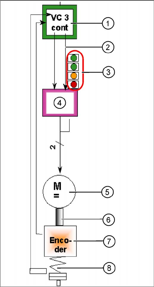
Axis control of Z axis
The Z axis is driven via a DC servo motor. Activation is
via a control signal (second control signal = 0) from the
VC3 controller I -target "W" and I -target "U" = 0. The in-
termediate circuit voltage is approx. 60 V.
1. Axis controller board A363 with VC3 controller (VC =
Velocity Commutation) or A 364
2. 1 control signal
3. LEDs on servo amplifier:
4. Servo amplifier
5. DC motor.
6. Between the motor and the incremental encoder
there is a fixed mechanical connection.
7. Read unit: transmits the exact position of the axis
(track signals).
8. Elastic mech. connection (belt) and light barrier
down, for fast recognition of the lower position.
The servo board controls the DC motor directly.