00194440-10_SM_X-Series_Customer_en.pdf - 第288页
Settings Axis Control 5.2.3 C&P6/12 288 Service Manua l SIPLACE X Series C&P12 – Z axis in free space C&P6 – Z axis Travel curves for Z axis of C&P12, in free space 1. Current target value: 2 V/D iv 2. Po…
Settings
5.2.3 C&P6/12 Axis Control
Service Manual SIPLACE X Series 287
Checking the Z Axis Dynamics
Measurement Setup
► Position the gantries so that the Z axis moves in a free space.
SITEST
► Select C&P heads ==> Select head ==> Axis functions
==> Select Z axis ==> Axis continuous run and edit the values in digits and accept. Target position
= 685; Positioning type = absolute.
Signal Example with the Vnom. Output
NOTICE
Same measurement procedure
The measurement procedure follows the same preparations and procedures as for the star ax-
is.
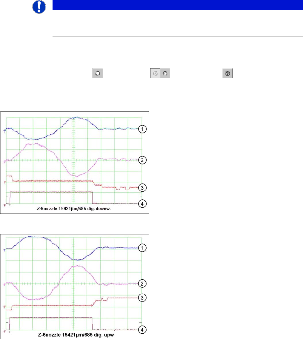
Dynamic signals Z axis, example of C&P6 shown
1. Control signal (at V nom. axis test box)
2. Uncommutated current signal at axis adapter
3. Deviation of position
4. End signal
Dynamic signals Z axis, example of C&P6 shown
1. Control signal (at V nom. axis test box)
2. Uncommutated current signal at axis adapter
3. Deviation of position
4. End signal
Settings
Axis Control 5.2.3 C&P6/12
288 Service Manual SIPLACE X Series
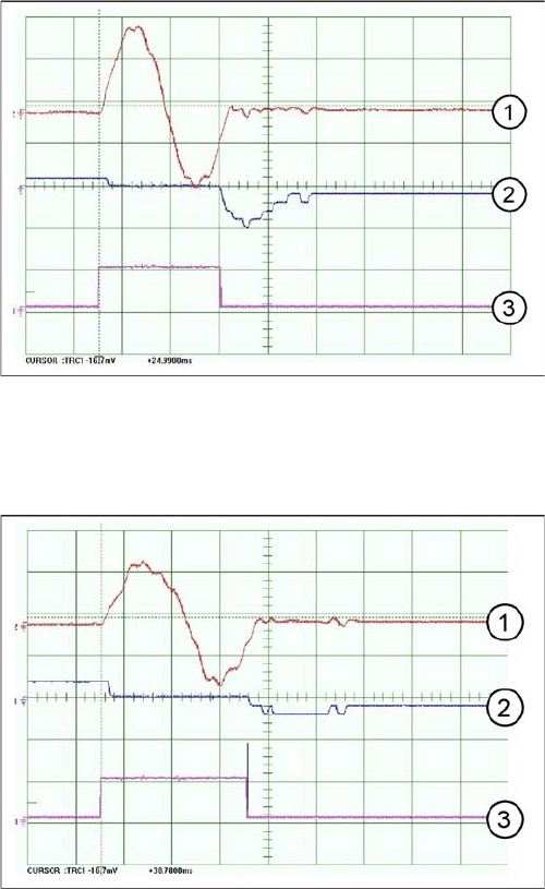
C&P12 – Z axis in free space
C&P6 – Z axis
Travel curves for Z axis of C&P12, in free space
1. Current target value: 2 V/Div
2. Position deviation: 500 mV/Div
3. End signal
Time basis: 10ms/Div
Path: 685 digits
Travel curves for Z axis of C&P6, in free space
1. Current target value: 2 V/DivWenz0900
2. Position deviation: 500 mV/Div
3. End signal
Time basis: 10ms/Div
Path: 685 digits
Settings
5.2.3 C&P6/12 Axis Control
Service Manual SIPLACE X Series 289
5.2.3.5
5.2.3.5 Axis Control of DP Axis
Axis Control of DP Axis
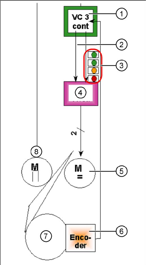
Axis control of DP axis
The DP axis is driven via a DC servo motor. Activation is
via a control signal (second control signal = 0) from the
VC3 controller I -target "W" and I -target "U" = 0. The in-
termediate circuit voltage is approx. 60 V. A stepping mo-
tor is used to couple the DP axis to the glass of the
segment. The DP axis positions the segment and is then
decoupled via the stepping motor.
1. Axis controller board A363 with VC3 controller (VC =
Velocity Commutation) or A 364
2. 1 control signal
3. LEDs on servo amplifier:
4. Servo amplifier
5. DC motor.
6. Read unit: transmits the exact position of the axis
(track signals).
7. Segment glass
8. Swivel in
The servo board controls the DC motor directly.