00194440-10_SM_X-Series_Customer_en.pdf - 第300页
Settings Axis Control 5.2.4 C&P20 300 Service Manua l SIPLACE X Series 5.2.4.4 5 . 2 . 4 . 4 A x is C o n t r o l o f Z A x is Axis Control of Z Axis Axis control of Z axis The Z axis DLM2 hea d is driven via a DC se…
Settings
5.2.4 C&P20 Axis Control
Service Manual SIPLACE X Series 299
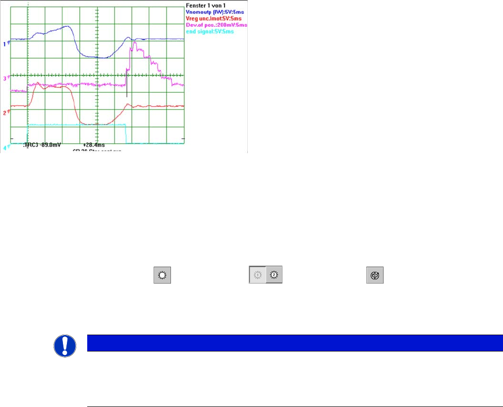
Signal Example with the Vnom. Output
The star axis dynamics are checked in the permanent star step mode. A motor phase current is emitted
at the Vnominal output of the axis test box.(control signal 1). The uncommutated current setpoint signal
(signal 3) shows no increased friction values for the axis.
The positioning time for the star axis is 28.5 ms +/-0.5 ms C&P20 (from 31.01.05).
SITEST:
► Select C&P heads ==> Select head ==>Axis functions
==> Select the star axis ==> Star continuous run
==> Entry: waiting period 500 ms ==> Accept.
► Press the START button if required.
Star axis dynamic signals for C&P20
The signals from top to bottom:
▪ Star phase motor current Iu measured at Vnom out-
put
▪ Uncommutated current signal Vreg (or PIN at axis
adapter)
▪ Deviation of position
▪ End signal
NOTICE
C&P20
If these dynamics should be significantly slower or if the uncommutated current signal should
deviate considerably, check the star axis mechanics for damage or the servo amplifier/axis con-
troller (other boards connected to the star) for electrical damage.
Settings
Axis Control 5.2.4 C&P20
300 Service Manual SIPLACE X Series
5.2.4.4
5.2.4.4 Axis Control of Z Axis
Axis Control of Z Axis
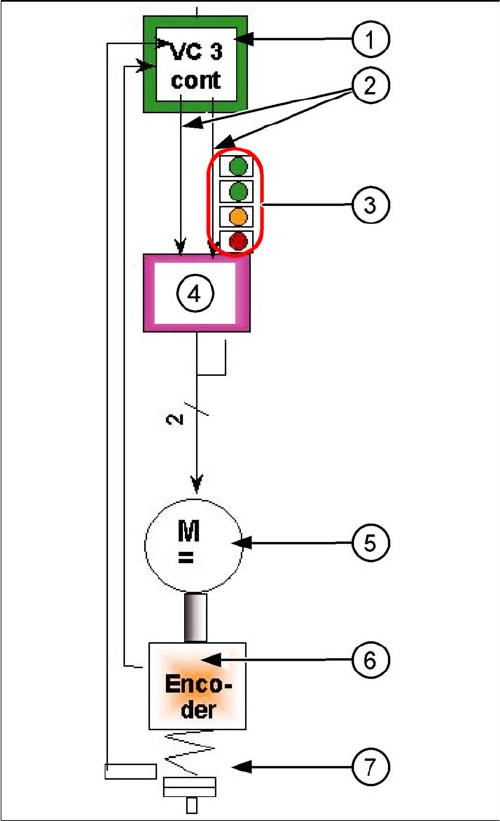
Axis control of Z axis
The Z axis DLM2 head is driven via a DC servo motor.
The C&P20 Z axis is driven via a 3~ AC drive. This acti-
vation is via two control signals phase from the VC3 con-
troller Itarget "W" and I-target "U". The intermediate
circuit voltage is approx. 24V.
1. Axis controller board A363 with VC3 controller (VC =
Velocity Commutation) or A 364
2. 1 control signal
3. LEDs on servo amplifier:
4. Servo amplifier
5. 3~ AC(DC) motor.
6. Between the motor and the incremental encoder
there is a fixed mechanical connection.
7. Read unit: transmits the exact position of the axis
(track signals).
8. Elastic mech. connection (belt) and light barrier
down, for fast recognition of the lower position.
The servo board controls the 3~ AC(DC) motor directly.
Settings
5.2.4 C&P20 Axis Control
Service Manual SIPLACE X Series 301
Checking the Z Axis Dynamics
Measurement Setup
The positioning time for the Z axis is 30 ms +/-3 ms (6 segment head) and 24 +/-1 ms DLM2 (for the 12
segment head) for 685 digits. The positioning time Z-C&P20 for 15 mm (equal to the DLM2 path) is
20 ms in both directions. For a path of 0-10000 digits (10 mm), the positioning time should be 16.7 ms.
Position the gantries so that the Z axis is above the calibration component position.
SITEST:
► Select C&P heads ==> Select head ==> Axis functions
==> Select Z axis ==> Axis continuous run Select and edit values in digits and accept. Target posi-
tion = 10000 digits (10 mm); Positioning type = absolute.
Signal Example C&P20 Z Axis with the Control Signal at Vnom. Output
NOTICE
Same measurement procedure
The measurement procedure follows the same preparations and procedures as for the star ax-
is.
Z axis dynamic signals for C&P20 -15.4 mm range
1. Motor phase current signal (
Vnom output
)
2. Uncommutated current signal V
reg
3. Deviation of position
4. End signal
15.4 mm (DLM2 path) positioning with the Z axis into free
space
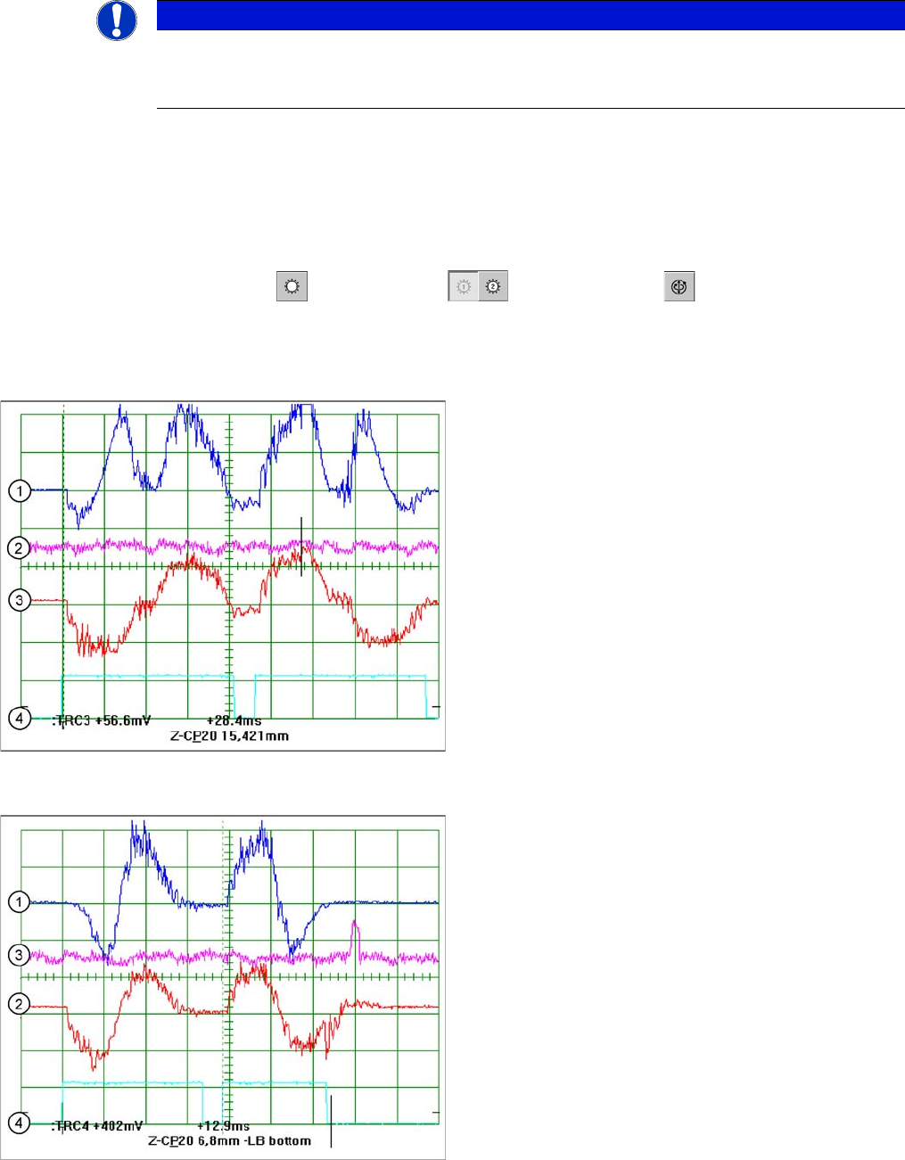
Z axis dynamic signals for C&P20 - calibration tool pocket
1. Motor phase current signal (V
nom
output)
, positioning up in each case
2. Uncommutated current signal V
reg
, positioning downwards
3. Deviation of position
4. End signal
6.8 mm positioning with the Z axis into the calibration tool
pocket