00194440-10_SM_X-Series_Customer_en.pdf - 第303页
Settings 5.2.5 TwinHead Axis Control Service Manual SIPLACE X Series 303 5.2.5 5 . 2 . 5 T w in H e a d TwinHead 5.2.5.1 5 . 2 . 5 . 1 O v e r v ie w o f A x is C o n t r o l f o r Z a n d D A x e s Overview of Axis Cont…
Settings
Axis Control 5.2.4 C&P20
302 Service Manual SIPLACE X Series
5.2.4.5
5.2.4.5 Axis Control of DP Axis
Axis Control of DP Axis
Checking the DP Axis Dynamics
Measurement Setup
The SIPLACE service technician can use special software to start a continuous function run and can, for
example, check the positioning times of the individual DP drives in SITEST (service password).
SITEST:
► Select C&P heads ==> Select head ==> Axis functions
==> DP Select the axis ==> Select Axis continuous run and enter the values in 1/100° (start position
0 – target position 18000) position time = absolute
= Start
⇨ The value shown for each individual DP drive should be less than 300 ms at 180°.
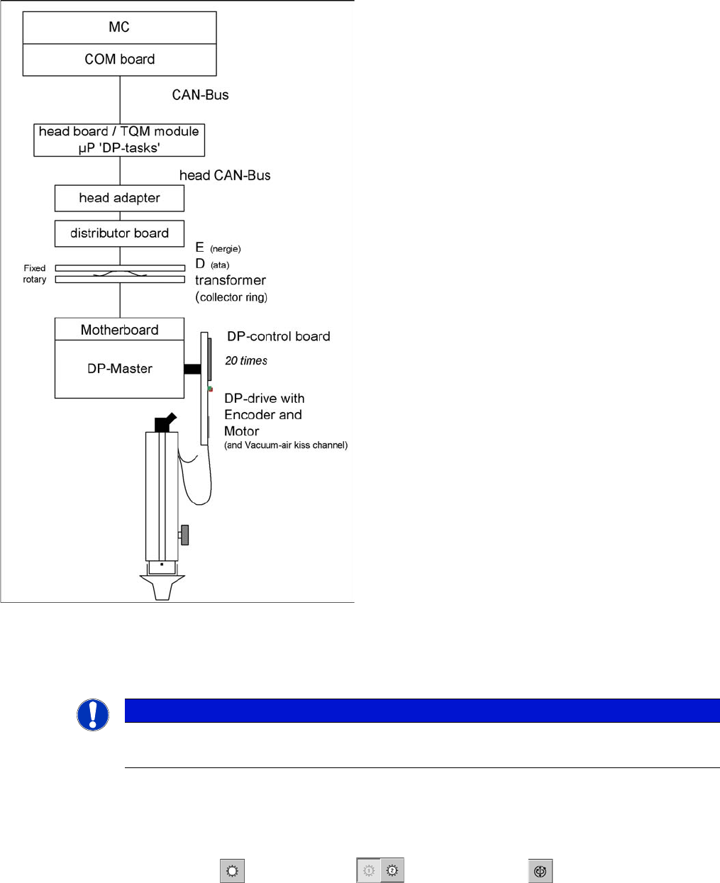
Axis control of DP axis for a C&P20 segment
The DP axis of the DLM2 head is driven via a DC servo
motor. The DP axes of the C&P20 segments are posi-
tioned by a DP masterboard and an "on board" direct
control unit. The control system uses CAN Bus at the re-
spective head board. The intermediate circuit voltage is
approx. 24 V. There is no swiveling in or out of a turning
station due to the direct drive in the segment drive motor.
The MC transmits the activation commands via the ma-
chine CAN Bus to the head processor.
This activates via four DP tasks and the head CAN bus
system with activation commands, via the
▪ head adapter
▪ intermediate distributor,
▪ the collector rings of the E/D transformer at the moth-
erboard with the DP motor.
The DP motor control in the segment is handled at the DP
control board with the help of count pulse from the inte-
grated HALL incremental encoder.
NOTICE
No measuring points
There are no measurement points accessible on the C&P20 rotary drives.
Settings
5.2.5 TwinHead Axis Control
Service Manual SIPLACE X Series 303
5.2.5
5.2.5 TwinHead
TwinHead
5.2.5.1
5.2.5.1 Overview of Axis Control for Z and D Axes
Overview of Axis Control for Z and D Axes
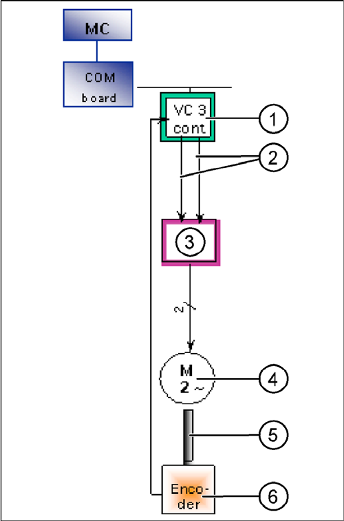
Axis control (shows D-axis as example)
The axis control system of the closed control loop for the
TwinHead consists of the following main components.
▪ Axis controller A363 with VC3 controller or A364
▪ Servo amplifier (SDS)
▪ Motor
▪ Position measurement system incremental scale and
encoder
1. Axis controller board A363 with VC3 controller (VC =
Velocity Commutation/speed commutation controller)
2. Control signals I nom "W" and I nom "U"
3. Servo amplifier function: motor current limiter dimen-
sioned by semiconductor or motor load - amplification
by axis controller signals. Determination of third mo-
tor current signal. Generation of three (2) AC motor
signals from the DC supply.
The Z/D servo output signals are directly connected
to the motors. This guarantees operator safety when
the safety covers are opened.
4. The Z axis has 3-phase AC motor with integrated
temperature sensor.
D axis has a 2-phase motor
5. The motor and the incremental encoder are fixed (rig-
id) to one another.
6. Incremental encoder: determines the exact position
of the axes, due to the track signals.
Settings
Axis Control 5.2.5 TwinHead
304 Service Manual SIPLACE X Series
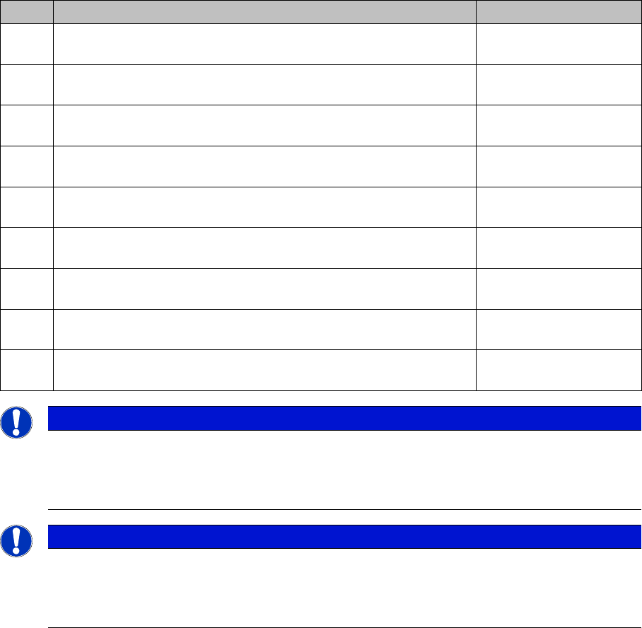
Overview of Positioning Times for TwinHead
Positioning times for TwinHead
Axis Mode/range Positioning time
Z Absolute positioning, free space/travel range 90000 digits = 45000
µm (resolution 0.5 µm)
75 ms +/-3 ms
Z Absolute positioning, free space/travel range 54200 digits = 27100
µm (resolution 0.5 µm)
57 ms +/-3 ms
Z Current sensor (for force measurement) on conveyor edge 516
nozzle travel profile 5, force 2 N
approx. 78 ms*
*see notes below
Z Current sensor (for force measurement) on edge of conveyor side
516 nozzle, travel profile 7, force 5 N
approx. 78 ms*
*see notes below
Z Current sensor (for force measurement) on conveyor edge 516
nozzle travel profile 7, force 10 N
approx. 65 ms*
*see notes below
Z Current sensor (for force measurement) on conveyor edge 516
nozzle travel profile 25, force 15 N
approx. 70 ms*
*see notes below
D 10000 digits = 10 degrees 90 ms +/-10 ms*
*see notes below
D 90000 digits = 90 degrees 150 ms +/-20 ms*
*see notes below
D 180000 digits = 180 degrees 190 ms +/-20 ms*
*see notes below
NOTICE
Z-Axis
The Z axis positioning time in the current or force sensor mode does not permit direct conclu-
sions about the functions. To check the function of these modes, you need to record oscillo-
grams or perform a force measurement during placement.
NOTICE
D axis
The positioning times between the left and right turns of the sleeve may deviate from one an-
other considerably. However, the time characteristic of the TwinHead in not critical, due to the
placement process.