00194440-10_SM_X-Series_Customer_en.pdf - 第315页
Settings 5.2.5 TwinHead Axis Control Service Manual SIPLACE X Series 315 Travel curves for D axis, 90 degrees rotation (to the right) TwinHead - D axis with 90 degrees rotation 1. Current tar get value 200 mV/Div 2. Posi…
Settings
Axis Control 5.2.5 TwinHead
314 Service Manual SIPLACE X Series
Checking the TwinHead D Axis Dynamics
Measurement Setup
The axis dynamics of the D axis are checked along various travel ranges.
SITEST
► Select TwinHead ==> Axis functions ==> Segment
==> Select DP axis ==> Axis continuous run ==> Edit and accept values:
Target position: 1000 1/100° = 10° = 10000 digits;
Positioning type: absolute.
Waiting period: 200 ms
► Press the START button if required.
NOTICE
Deviating positioning times
The positioning times between the left and right turns of the sleeve may deviate from one an-
other considerably. However, the time characteristic of the TwinHead in not critical, due to the
placement process.
NOTICE
Same measurement procedure
The measurement procedure follows the same preparations and procedures as for the Z axis
Travel curves for D axis with 10 degrees rotation
TwinHead - D axis with 10 degrees rotation
1. Current target value 200 mV/Div
2. Position deviation 500 mV/Div
3. End position signal 5 V/Div
Target positioning time: approx. 90 ms +/-10, path 10000
digits
Time basis: 50ms/Div
Settings
5.2.5 TwinHead Axis Control
Service Manual SIPLACE X Series 315
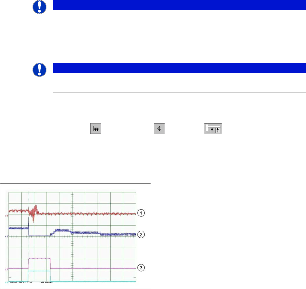
Travel curves for D axis, 90 degrees rotation (to the right)
TwinHead - D axis with 90 degrees rotation
1. Current target value 200 mV/Div
2. Position deviation 500 mV/Div
3. End position signal 5 V/Div
Target positioning time: approx. 160 ms +/-20, path
90000 digits
Time basis: 50ms/Div
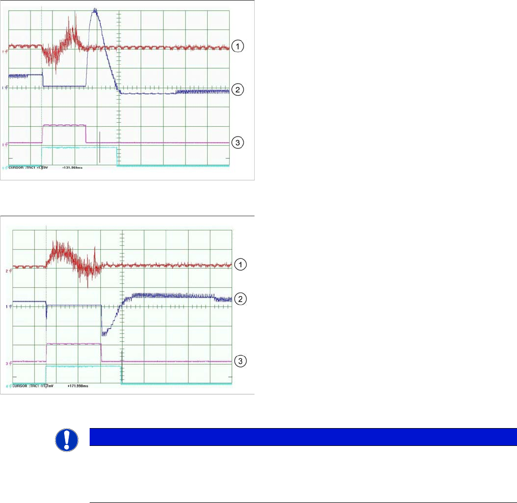
Travel curves for D axis with 180 degrees rotation
TwinHead - D axis with 180 degrees rotation
1. Current target value 200 mV/Div
2. Position deviation 500 mV/Div
3. End position signal 5 V/Div
Target positioning time: approx. 200 ms +/-20, path
190000 digits
Time basis: 50ms/Div
NOTICE
Positioning times
The positioning times for the D axis of the TwinHead are not critical, from a placement perfor-
mance perspective, provided the positioning time is below 230 ms. If the time is above this, this
will affect the placement performance.
Settings
Nozzle Changer Setting 5.3.1 Setting the Height of the Nozzle Changer for the C&P20A
316 Service Manual SIPLACE X Series
5.3
5.3 Nozzle Changer Setting
Nozzle Changer Setting
5.3.1
5.3.1 Setting the Height of the Nozzle Changer for the C&P20A
Setting the Height of the Nozzle Changer for the C&P20A
Parts, equipment and tools
▪ Measuring scale
▪ NC shim plate [03021079-xx]
Overview
Setting
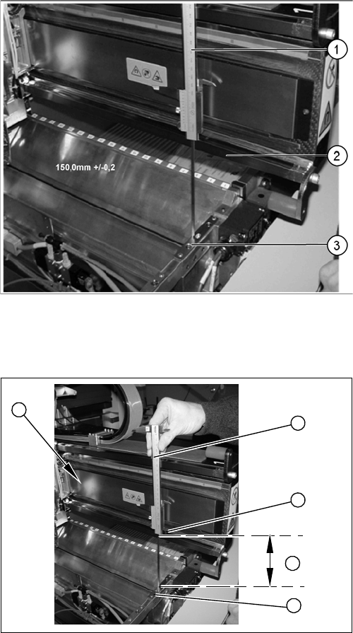
Setting the nozzle changer for C&P20A
1. Measuring scale
2. Top edge of the X axis lower linear guide
3. Fitting surface for nozzle changer
In order to guarantee the safety gap between the head
(component sensor) and nozzle changer, the contact sur-
face of the nozzle changer on the docking unit is set to a
distance of 150.0 mm +/-0.2 mm to the X axis linear guid-
ance, with a measuring scale. The height of the fitting sur-
face on the docking unit is adjusted with the help of shim
rings. The nozzle changer can then be fitted.
1. Measuring scale
2. Top edge of the X axis lower linear guide
3. Values to be set (150 +/- 0.2 mm)
4. Nozzle changer contact surface
► During the following inside measurement, make sure
that the tip of the measuring scale does not tough the
magnetic strip, as this might scratch it!
► Position the measuring scale (1) on the top edge of
the X axis lower linear guide (2) and measure the dis-
tance to the nozzle changer contact surface (4).
► Hold the measuring scale vertically (1).
► The setting value (4) is 150 +/-0.2 mm.
Add or remove shims as required.
► Repeat this measurement on the inside of the gantry
(5).
► Calibrate the position of the nozzle changer.
5
1
4
3
2