00194440-10_SM_X-Series_Customer_en.pdf - 第32页
Overview of the Modules Electrical System 2.2.2 Computer Unit [03002110-xx] 32 Service Manual SIPLACE X Series 2.2.2 2 . 2 . 2 C o m p u t e r U n it [ 0 3 0 0 2 1 1 0 - x x ] Computer Unit [03002110-xx] Overview The bac…

Overview of the Modules
2.2.1 Axis Units Electrical System
Service Manual SIPLACE X Series 31
2.2.1.9
2.2.1.9 Example for Axis Unit A364
Example for Axis Unit A364
Axis unit with two C&P20 in placement area 1
1. Power supply +/- 15V, +5 V
2. Ballast circuit, only in axis unit PA2
3. Power supply +/- 15V
4. Fan unit (blows downwards)
5. Axis card A364 for gantry 1/2
6. Axis card A364 for gantry 4/3
7. Servo amplifier X axes
8. Servo amplifier Y axes
9. Brake board for each X axis and Y axis
10. Servo star axis (2x)
11. Servo Z axis (2x)
12. DC/DC converter DP drives (2x)
13. Placement area 1 gantry 1 (top half)
14. Placement area 1 gantry 4 (bottom half)
Overview of the Modules
Electrical System 2.2.2 Computer Unit [03002110-xx]
32 Service Manual SIPLACE X Series
2.2.2
2.2.2 Computer Unit [03002110-xx]
Computer Unit [03002110-xx]
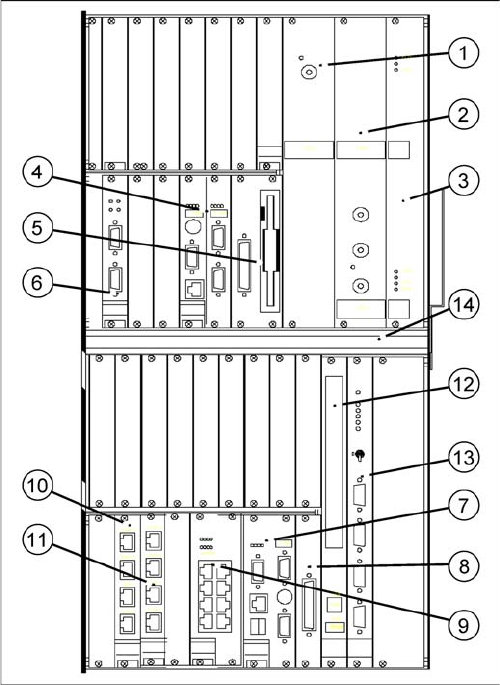
Overview
The backup battery 3.6 V is located at the back of the computer unit (on the outside of the rear panel
wiring board).
Power supply / DC-DC converter
1) Input +52 V / output +3.3 V, 20A
2) Input +52 V / output +5.0 V, 60A
3) Input +52 V / output +/- -12 V, 6A
Machine control (MC)
4) CPU
5) HD/FD drive
6) CAN COM unit – connection above for PA1 / connec-
tion below for PA2
Control computer for station and Vision computer func-
tions (SR)
7) CPU
8) HD drive
9) 2 x LAN interfaces for communication to the MC and
SIPLACE Pro computer
10) 4 x hotlink interfaces for Vision functions /hotlink
card1: PA1
11) 4 x hotlink interfaces for Vision functions /hotlink
card2: PA2
Other
12) CD-ROM drive with USB connection
13) Video multiplexer
14) Fan unit
Overview of the Modules
2.2.3 Computer Unit with BoxPC Electrical System
Service Manual SIPLACE X Series 33
2.2.3
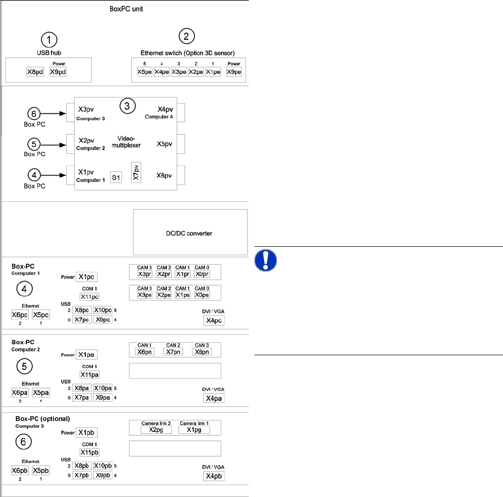
2.2.3 Computer Unit with BoxPC
Computer Unit with BoxPC
Computer unit with BoxPC [00351894-xx]
X series placement machines from machine number 600
onward and in X4I machines are equipped with box PCs
in the computer unit.
Depending on the machine type and the configuration up
to three box PCs are used.
Position of assemblies in the computer unit
1. 4 port USB hub 2.0
2. Ethernet switch (only for optional 3D sensor)
3. Video multiplexer
4. Computer 1:
Station computer (up to SW 60x)
Vision computer (from SW 70x)
5. Computer 2:
Machine controller (MC) (up to SW 60x)
Station computer / MC (from SW 70x)
6. Computer 3:
Additional box PC - only for optional 3D sensor (not
for X4I)
NOTICE!
An external DVD drive is supplied with the delivery pack-
age.
From SW702 (X series from SW703) onwards, X4I ma-
chines are supplied with higher performance BoxPCs
[03072079-xx]. This means that machine control and the
Vision function are handled by only one BoxPC.