00194440-10_SM_X-Series_Customer_en.pdf - 第331页
Settings 5.4.5 Setting the Laser Light Barrier for the Stopper Position C onveyor Settings Service Manual SIPLACE X Series 331 5.4.4.1 5 . 4 . 4 . 1 A d ju s t in g t h e L im it S w it c h f o r I n it ia liz in g t h e…
Settings
Conveyor Settings 5.4.4 Checking the Limit Switch Position
330 Service Manual SIPLACE X Series
5.4.4
5.4.4 Checking the Limit Switch Position
Checking the Limit Switch Position
► Check the minimum and maximum width and ensure that the conveyor edges are parallel.
Values
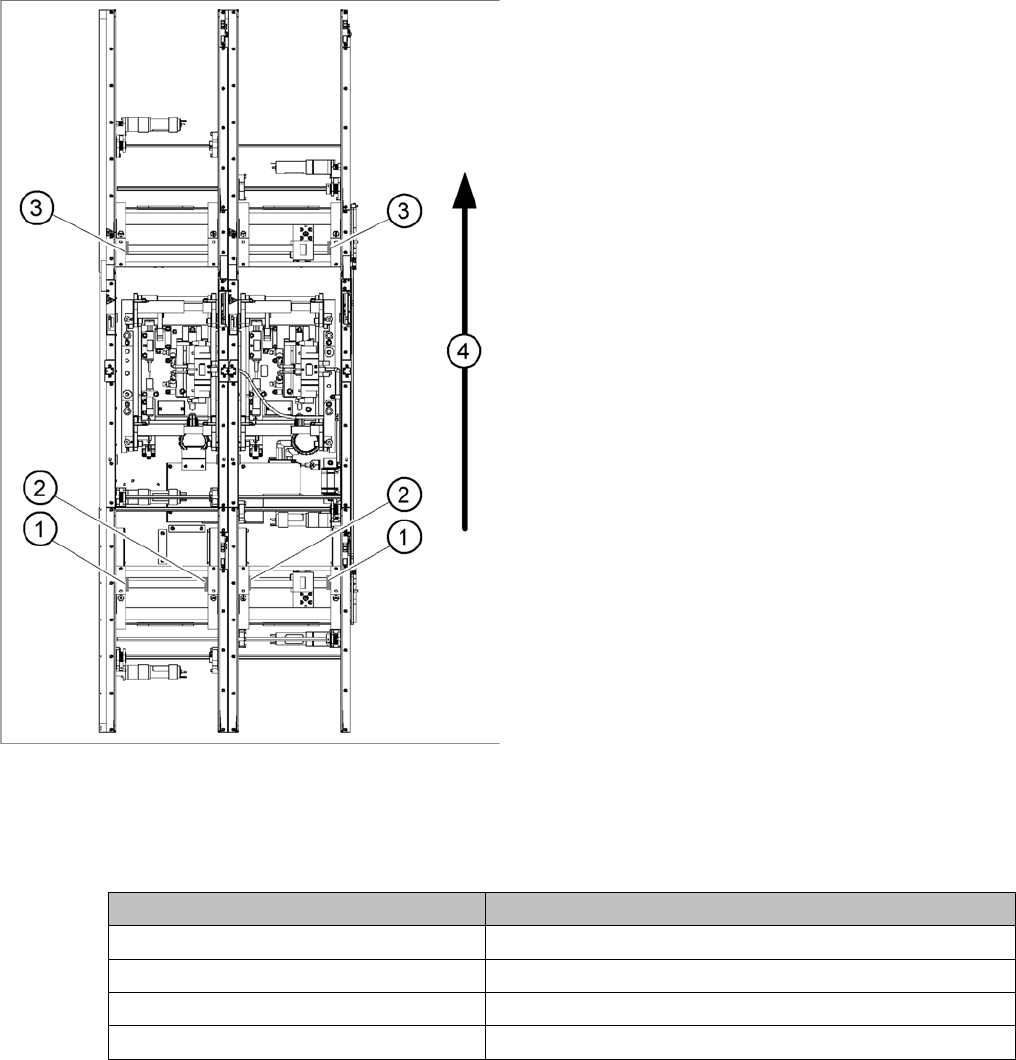
Position of the width adjustment and conv. side limit
switches (symbolic draw)
1. Limit switch on the input conveyor - fitted below the
conveyor edge
2. Limit switch on the input conveyor - fitted below the
conveyor edge
3. Limit switch for the width adjustment unit
4. Transport direction
▪ Limit switches in input conveyor:
There are five limit switches below the conveyor edg-
es near the input conveyor. The limit switch is de-
signed to prevent the conveyor edges hitting one
another or the conveyor frame.
▪ Limit switch in output conveyor:
In the vicinity of the output conveyor there are two
limit switches for the adjustment unit. They serve to
protect the traveling range and initialize (right side)
the adjustment unit for the width adjustment.
Setting Value
Minimum width: 49.7 mm
Maximum width single conveyor: 508.5 mm
Maximum width of dual conveyor 216.5 mm (standard)
Maximum width of dual conveyor 242.5 mm (Standard)
Settings
5.4.5 Setting the Laser Light Barrier for the Stopper Position Conveyor Settings
Service Manual SIPLACE X Series 331
5.4.4.1
5.4.4.1 Adjusting the Limit Switch for Initializing the Adjustment Unit
Adjusting the Limit Switch for Initializing the Adjustment Unit
5.4.5
5.4.5 Setting the Laser Light Barrier for the Stopper Position
Setting the Laser Light Barrier for the Stopper Position
Tools
▪ [00369205-xx] Setting gauge for laser light barrier
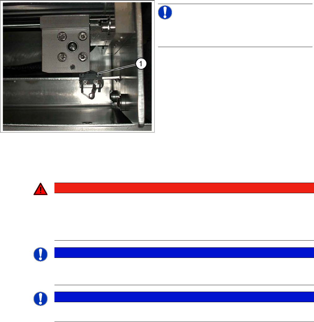
Limit /initialize switch
NOTICE!
This setting is only required after replacing the switch or
other error functions in the width adjustment reference
run.
► Move the adjustment unit for the width adjustment by
hand (via the toothed belt) to the conveyor edge.
► Loosen the two screws on the limit switch (1).
► Move the limit switch in the slot towards the adjust-
ment unit and make sure, that the limit switch is safely
switched on.
► Check the switching state of the corresponding LED
(H11 for TSP 201) (H41 for TSP 301) in the conveyor
control software.
► Fit the limit switch in this position.
► Calibrate the conveyor width via the SITEST pro-
gram.
DANGER
Laser class 2
The laser light barrier transmitter emits class 2 laser beams. You do not need to take additional
protective measures!
► However, you should never look into the laser beam.
► Adjust the LASER diode beam only from the rear side of the LASER (left machine side).
NOTICE
Setting the maximum conveyor width
The laser beam deflection has greatest effect at the maximum conveyor width, it should always
be calibrated at the maximum conveyor width.
NOTICE
PCB Reference Corner
After setting the laser light barrier you must check or re-teach the PCB reference corner!
Settings
Conveyor Settings 5.4.5 Setting the Laser Light Barrier for the Stopper Position
332 Service Manual SIPLACE X Series
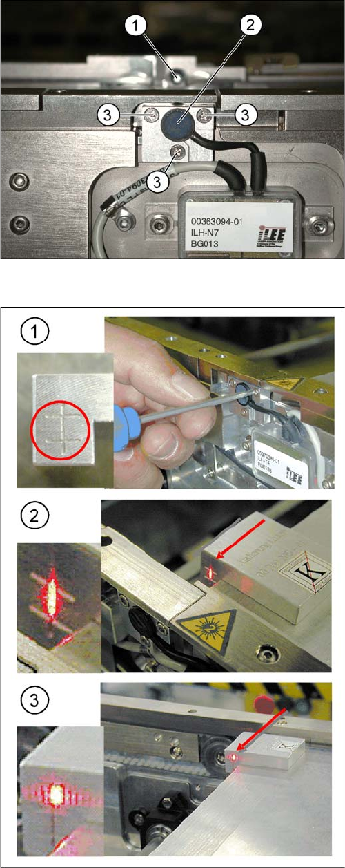
Overview
Laser light barrier
1. Laser receiver
2. Laser diode
3. Setting screws (3x)
Focussing the laser beam
1. Setting the laser light barrier
2. Minimum width
3. Maximum width
Procedure
► Set the maximum conveyor width.
► Select Enable safety mode.
► Activate the relevant laser diode using the input/out-
put functions in the station software.
► Check the path of the laser beam with the help of the
gauge.
► With the help of the three setting screws, adjust the
laser beam to the center of the gauge cross (1).
► Now position the conveyor to minimum width (2) and
check the setting.
► Check the PCB reference corner and reteach, if nec-
essary.