00194440-10_SM_X-Series_Customer_en.pdf - 第334页
Settings Conveyor Settings 5.4 .6 Board Clamping Functions 334 Service Manua l SIPLACE X Series 5.4.6.1 5 . 4 . 6 . 1 S e t t in g B o a r d C la m p in g Setting Board Clamping Setting actua tor 1. Setting Gauge fo r Ac…
Settings
5.4.6 Board Clamping Functions Conveyor Settings
Service Manual SIPLACE X Series 333
5.4.6
5.4.6 Board Clamping Functions
Board Clamping Functions
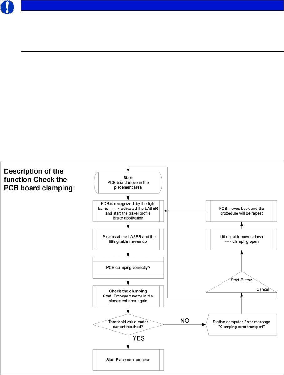
Function description:
▪ The PCB moves into the placement area, it is recognized by the light barrier, stops at the laser and
the lifting table moves up.
▪ Check PCB clamping: The transport motor in the placement area start again. If the PCB is clamped
correctly the motor current will rise up and reach a defined threshold value. Once the board has been
correctly clamped into place, the placement process will begin.
▪ If this threshold is not reached, the system assumes that the board is on its way to the intermediate
or output conveyor and has therefore not been correctly clamped into place.
▪ The station computer will issue the message "PCB not correctly clamped PA1 (PA2)". The process
can be repeated by pressing the "start button".
▪ The lifting table will move downwards, the board will be transported back and the stopper position
will be approached again.
NOTICE
The check whether a PCB is clamping correctly, is controlled with a motor current check of the
transport motor if the PCB board is clamped (Lifting table up). To check the function you could
put a distance plate under the conveyor side edge, so that the lifting table can not move to the
upper position.
The check is not performed if the option "Vacuum Tooling" is installed.
Settings
Conveyor Settings 5.4.6 Board Clamping Functions
334 Service Manual SIPLACE X Series
5.4.6.1
5.4.6.1 Setting Board Clamping
Setting Board Clamping
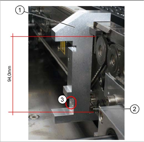
Setting actuator
1. Setting Gauge for Actuator [03049740-xx]
2. Actuator
3. Drilling, for fixing the actuator screws, when the
gauge is fitted
If the conveyor control issues the error Clamping error
conveyor, you need to check the distance from the lifting
table actuator to the upper edge of the conveyor belt.
Use the setting gauge to check and set the actuator. The
distance from the clamping actuator (lifting table) to the
top edge of the belt should be 94.0 mm at all four contact
points. (see diagram)
Settings
5.4.6 Board Clamping Functions Conveyor Settings
Service Manual SIPLACE X Series 335
5.4.6.2
5.4.6.2 Setting the Board Clamping
Setting the Board Clamping
► To check whether the board clamping is functioning properly, clamp a board with the lifting table.
Then check whether the board is clamped tightly on the side.
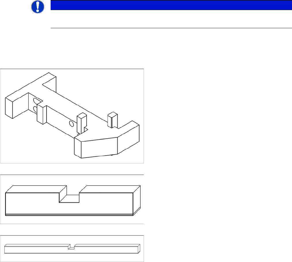
Tools
Setting (single and dual conveyor)
► The terminal strip may need to be modified, depending on the machine type. As the S27 only has a
maximum clamping area of 74 mm, the terminal strip needs to be fitted on the correct side. The ter-
minal strip for X series, HS-60 and D series machines needs to be set to 94 mm. Fit the terminal
strip accordingly on the gauge.
► The gauge is inserted between the actuator and the clamp.
► The actuator can now be released, moved down and then tightened again through the holes provid-
ed.
NOTICE
Only in the event of problems
This setting should only be made if there are problems with the clamping.
The clamping function is set with the "Adjust gauge actu-
ator cpl" [03049740-xx].
▪ Terminal strip for S27, HS-60, HF, X2, X3, X4
[03049739-xx]
▪ Long terminal strip for X4I [03076698-xx]